This thread has been locked.

If you have a related question, please click the "Ask a related question" button in the top right corner. The newly created question will be automatically linked to this question.

TPS62740: Power consumption issues at no load conditions

Part Number: TPS62740
Other Parts Discussed in Thread: BQ24050

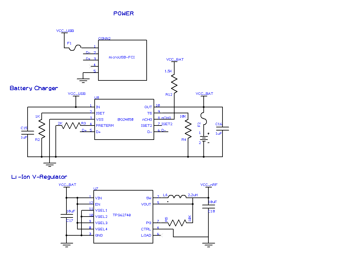
We are using the TPS62740 to power a Nordic nRF chip from a Li-Poly battery source. We are measuring an abnormally high current being drawn by the TPS62740 when there should be almost no load on the Vout pin.

For our test we power the TPS62740 with 4V from a power supply connected to the Vin pin (Vcc-bat rail) in the schematic and monitor current. With the nRF in sleep mode and no load on the Vout pin (Vcc_nRF rail) we measure a current draw of about 200 uA on Vcc_bat. 

We removed the TPS62740 from our board and powered the nRF chip with 3V from the power supply directly to the Vcc_nRF rail and measure 2-5 uA of current. We have done this test on 3 separate boards and gotten the same result each time.

We removed the battery charger chip BQ24050 and did not measure a significant change in the lower power current draw of 200 uA.

Does anyone know possible reasons for this extra current draw through the TPS62740? 

Are there issues with our schematic?

Are there other tests we should try to help with debugging?

Thanks very much for your help.

  • This is a good debugging exercise. This app note, from the product page, may have some useful information: www.ti.com/.../slyt558.pdf

    For sure, you need to look at Vin, Vout, and PG with a scope to make sure they are DC and at the voltages that you think they are at.
  • Chris,

    Yes, understood about good measurement practices. I read your application note and we are following best practices for our setup. I re-checked Vin, Vout, PG and there are stable and at 4V, 3V, and 3V.

    The current consumption differences are large: 200 uA through the TPS62740 and 5 uA when connected direct to the nRF. So I don't think the extra current consumption is coming from our test setup.

    Is there any issue in the schematic design that you can see? Other suggestions?

    Thanks.
  • I recommend looking at those signals with a scope, not just a meter.

    The schematic looks fine. You can compare your measurement to the same measurement on an EVM to see if it is test setup related or some issue with your circuit.
  • Chris,

    Thanks. We found the low power issue was not due to the TPS62740 operation. While re-working another component on our PCB, the heat from the hot air gun fried the TPS regulator so that it was no longer holding a steady 3.0V.

    We have encountered a separate issue with the TPS62740 regulator at no load conditions. When our system is in normal operation, it pulls 4-10 mA of current and the TPS supplies a constant 3.0V. When we put our system to sleep, the TPS V_out will vary with the V_in voltage level.

    If V_in voltage below 3.5 V, then V_out will be steady at 3.0V

    If V_in is 3.5V to 4.1V, then V_out equals V_in - 0.5V

    In sleep mode, the load current is about 50 uA. 

    Is this expected operation of the TPS? Our system is operating on a Li-Poly rechargeable battery, so we will have V_in vary up to 4.1 V. 

  • No, this is not normal. You need to look at the waveforms with a scope. The IC may be damaged again.
  • We are scoping and will let you know what we find.

    Another question- we have the nCHG pin with a pull-up resistor to the V_bat rail as suggested in the datasheet. We are monitoring that nCHG pin with a microcontroller I/O pin that should be limited to 3.0 V. However, the V_bat rail will vary from 3.3 - 4.1 V depending on the battery charge.

    Can we use a pull-up from nCHG to our V_cc rail at 3.0 V? Do you see any issues with that?

    Thanks.
  • This looks ok, but the battery charger team needs to confirm, through a new post with their part number in the title in their forum.
  • Okay. I will repost. Thanks.