This thread has been locked.

If you have a related question, please click the "Ask a related question" button in the top right corner. The newly created question will be automatically linked to this question.

LP8543: Overcurrent fault

Part Number: LP8543

We are using this driver in stand alone mode to drive sharp LS037V7DW05 display backlight.  Device is rated at 60C and we are seeing intermittent backlight shutdowns at 60C with Driver reporting overcurrent condition. 

Usually problem goes away at low temperature.  However i have a board where LP8543 reports overcurrent immediately upon startup.  We are trying to determine if LP8543 is damaged.  

VPROG[4:0] is 0 indicating Vout is at 10V.

input is dual cell lithium so 8.4V.  I measure at around 8V at J10 during fault.

Current select is 0x55 (20mA)

Fault register 0x02 indicates 0x0C driver is on and overcurrent. If i disconnect the display I get 0x08

bad unit also shows 38V with no display connected. A good unit shows around 30V with no display connected.

I first though that Shottky was blown, as it is clearly inadequately specified.  However, even after replacing with a new one, problem still remains.

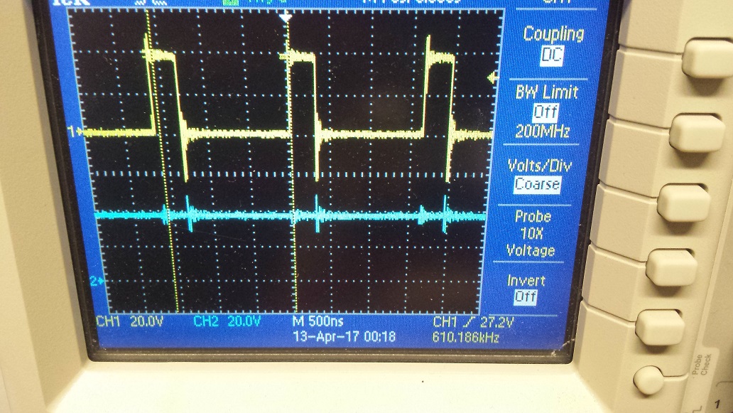
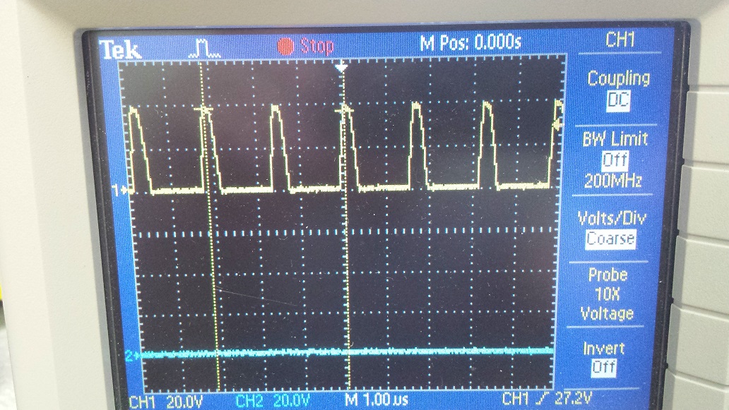
Switching works with no load, I see the switching waveform across the shottky.   This is not a configuration issue as most devices work up to 40C. 

Is the part damaged?

  • Hi,

    I'm not an apps engineer assigned to this device though I'm not an expert on it.

    When OCP fault happens, boost switching stops until OCP condition is cleared. During OCP fault, boost output voltage will be Vin - Schottky diode drop due to no boost SW operation.

    And disconnecting load while device is enabled will clear OCP condition and boost will start switching, but adaptive loop will try to find correct voltage at OUTx pin, and boost out voltage will go up to max voltage(38V) as LED load is disconnected. 38V from bad unit seems normal operation.

    I'm not sure how you can see 30V from good unit. I guess initial boost voltage setting is 30V from ADDR 0xBD[4:0] = VPROG[4:0]? if VPROG setting is 30V, boost will stay at 30V at power up if LED load is disconnected before power up. If LED load is disconnected during normal operation, you will see 38V as well.

    I think one possibility is different OCP setting between good and bad devices.

    Please check EEPROM addr 0xBD[6:5], and increase it if it's lowest setting

    Even if OCP setting is same with other devices, SW current may have a little variation in the device due to SW time and Rdson of internal SW FET.

    At high temp conditions, these internal characteristics will work to increase power loss and die temperature, and result in OCP fault.

    If you don't see any difference after you increase OCP limit, it may be a real damage on device.

    Hope this helps,

  • Thank you. that helps. I am not able to write to that register. I'm reviewing the datasheet to see how to do it properly, but its not very clear how to update contents of EEPROM. Sample code would have been helpful.
  • Hi,

    I don't know exactly how to program this device because this is kind of old design, but it seems there is no unlock procedure to program EEPROM.

    So, I would try this sequence.

    I2C slave address : 0x2C(7 bit), 0x58(8 bit, write), 0x5A(8 bit, read)

    EEPROM address      data

                0xBD               0xXX(to program bits[6:5] with higher values

                0x72                0x02 (EEPROM programming)

    wait a few hundred usec

                0x72                0x09 (EEPROM values download to registers - SRAM)

    Hope this helps,

  • Thanks for the info.  We are looking into getting new setting to stick in the EEPROM memory location.  In the meantime, i managed to damage another LP8543 by accidentally shorting LCD_LED+ and LCD_LED- pins with the scope probe.  Now the driver immediately shows over current fault.   I believe this might be the second board where this happened.  Why is it that if back light output pins are shorted, device gets damaged.  Damage is the same as i originally mentioned.  Over current fault is reported as soon as LED load is present.   One more thing id like to mention is that D27 is only 30V reverse breakdown diode.  We are replacing it with a 60V shottky.  We believe this diode's reverse leakage current is what causes the over current fault at elevated temperatures.  See scope shopt below of voltage across the shottky. However in order to prove this,  I need to get the board back to operational state.  I need to replace the driver IC and even more importantly find out why device is damaged when output pis are shorted. 

    Scope shot below shows voltage across D27.   

  • Hi Petar,

    Sorry to hear about EVM damage.

    This device doesn't have power line control for output short case, so huge current by this short can flow through before internal SW FET is turned off.

    Another possibility of the damage by Vout and LED pin short may come from voltage spike on LED pin higher than its abs max voltage rating. LED driver's voltage rating is supposed to be higher than max Vout voltage, but mechanical touch may cause voltage spikes going into these pins and damage LED driver block.

    I think your assumption for the OCP issue by diode also makes sense. Diode may be turned on in reverse direction and output current can be shorted during SW on time.

    It seems you're using only 1 channel out of 7 LED channels. There are many other simple LED drivers can support your apps condition as I know. Is there any reason you need to use this device? It may help our product line, but may not be so efficient usage of this device.

    I hope new diode would fix the issue.

    Thanks,

  • Thanks for the info.  This is very useful.  For a new design we will make better design choices.  Unfortunately this is a shipping product that has issues and we are trying to fix them.  So changing the IC is not feasible.  But as far as this driver, i believe you have answered all of our inquiries so thank you very much.

    I am changing out the damaged IC on a high temeprature board, and will be putting in a 60V shottky before we re-test.

    Even at room temperature with the 60v shottky SW to GND waveform looks much better.

    Waveform at SW with 30V shottky is shown in yellow (top waveform) below. note that SW goes -20V due to D27 breakdown.

    Waveform at SW with 60V shottky, note that SW stays at ground as opposed to going negative due to caps discharging via reverse biased D27.