This thread has been locked.

If you have a related question, please click the "Ask a related question" button in the top right corner. The newly created question will be automatically linked to this question.

TPS61088: TPS61088

Part Number: TPS61088

Regarding Boost Converter


We want two different output voltage value from Boost converter as per condition.

When Lithium Ion Battery present i.e. Vin 3.0 V to 4.2 V (Battery Capacity 10050 Ah) should give output voltage 5 V & 5A

When Dc supply present i.e. Vin 5 V to 5.5 V should give output voltage 9 & 3A
​ 
We have used switch after Boost converter to select voltage when both DC 5V and Battery present or only Battery or only DC 5V present.

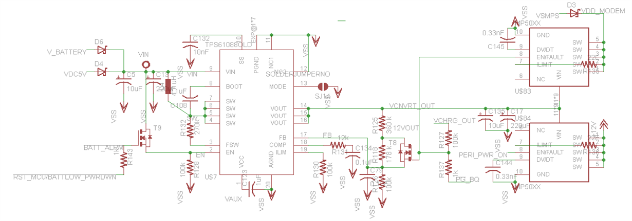
Please find attached Schematic and board file for the same.

Problem: IC gets heated eve though thermal pad is properly soldered. and after connecting load IC stops working. It shows short at SW pin to ground. SW pin gets shorted with ground. Like this I have burnt many ICS. I also tried by 12 V output when DC input present still ic gets shorted after applying input voltage.

I tried by changing inductor value. Following inductor option i have tried. 

ASPI-0630HI series I have used. 

ASPI-0630HI-4R7--- 4.7 uH

ASPI-0630HI-​1​R​0​--- ​1​ uH
​​
​two inductors In series ​ ASPI-0630HI-4R7--- 4.7 uH and ASPI-0630HI-​1​R​0​--- 1 uH​

​two inductors In series ​ ASPI-0630HI-4R7--- 4.7 uH and ASPI-0630HI-4R​7​--- 4.7 uH

  • Dear Sir,

    I got your brd file but can't open it. Here're my suggestion before pcb review.


    0. Make sure there's no soldering issue!
    1. Suggest you use 2.2uH indcutor based on your frequency setting.  If you only have 1uH indcutor, then you can increase the frequency to 0.75-1MHz.
    2. To make sure the frequency setting is OK, put the mode pin to GND. test the SW signal at no load to check the frequency right or not. When mode pin short to GND. the SW signal should be the setting frequency at any load.
    3. measure the impendanace from the Ilim pin to GND, make sure it is 100k. or you need to reconnect it.
    4. Make sure the current rating of the indcutor is higher than 8A based on your 9V/3A output.
    5. What is the capacitor from the FB pin to GND? this cap can't be too big. must be <100pF or remove it.
    6. Compennsation network: Comp should be change to 10nF, 100nF is too big.
    7. Measure the the output volatge under no load condition, if the output Vo is right. then add the load current step by step to check the output voltage change.

    Please do according to my above suggestion. Hope you can found something wrong soon.

  • The inductor should be OK!


    Did you catch the waveform of the TPS61088, such like the SW waveform, inductor current, output voltage? These waveform can help to find the root cause!


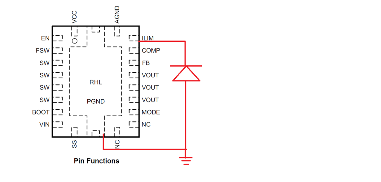
    Here I suggest you check the soldering of the Ilim pin, there’s a parallel diode from GND to Ilim, so you can test it out from GND to any trace connect with Ilim. If you can’t test that diode, then Ilim pin is not well soldered. So the inrush current will be very big(That’s why I request the inductor waveform).