- Ask a related questionWhat is a related question?A related question is a question created from another question. When the related question is created, it will be automatically linked to the original question.
Hello!
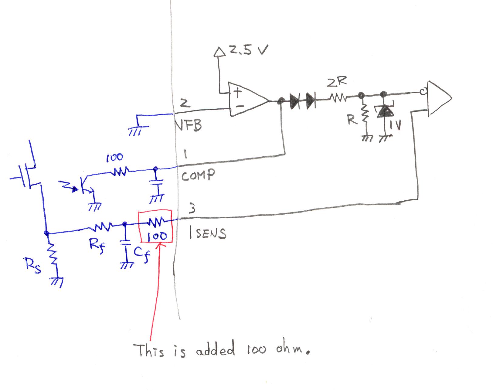
I use the TL2842B with the fly-back circuit.
The composition of the current detection circuit is equal to Fig-2 in the TL2842B datasheet.
The VFB-pin is connected to GND.
The COMP-pin connects the phototransistor through the 100Ω.
(The emitter of the phototransistor is connected to GND.)
An intermittent oscillation has been generated at a light load.
However, when the 100Ω is connected between Rf/Cf and ISENS-pin of Fig-2,intermittent oscillation is improved.
Can you explain this phenomenon?
I was not able to do.
And,is this good method?
Could you please help me?
Best regards.
Masahiro