This thread has been locked.

If you have a related question, please click the "Ask a related question" button in the top right corner. The newly created question will be automatically linked to this question.

BQ34Z100-G1: Bq34z100-g1 current calibration , strange sense resistor value

Part Number: BQ34Z100-G1

I have connected 10 parallel 5miiliohm sense resistors, making 500microohm sense for in bq34z100-g1 circuit.
After current calibration in bq34z100-g1, the value of CC Gain & CC Delta comes out to be 18.219 miiliohm. I have used current divider of 5, so as actual current was -1000mA, I had entered -200mA.

Query is actual sense is 500microohm, while after calibration it appears to be so high? I am using divider of 5, so according to be after calibration value should be around 500microohm*5 = 2.5miiliohm, somewhere near it.
But it comes out to be 18.219 miiliohm.
Is there anything I am doing wrong?

  • That does look like something is wrong. The CC Gain and CC Delta should be close to 2.5 mohm. How are the resistors connected together? There must be a connection problem or connection resistance in the network.

    • Hi,
    • It is not recommanded to use so many resister in parallel. This will introduce many noises in the test. Is it because that you are using very huge current?
    • It is also not recommanded to use a resister small than 0.005 ohm and this will make the influence the accuracy of colomb counter.
    • How much current will flow across the gauge sense resister? If the voltage between the sense resister is not over 125mV (For 0.005 ohm resister, it is 25A), The gauge can works well. So you can keep the parameters as default. 

  • Hi,

    1. I have two board, one is complete soldered with all sense resistors & one board with only bq34z100-g1 with single sense. Both have this problem, actual sense & CC gain are very apart after calibration. Single sense is 5milliohm.

    2. I have passed certain current though board & check voltage drop directly across sense, it seems ok. That means sense value is ok.

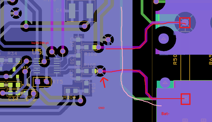
    3. In attached pic:
    a) Two red rectangle is where sense is connected
    b) two red wires , drawn loosely over gerber, shows the sense resistor connection to R106 & R105, which goes to U5 i.e bq34z100-g1.
    c) One pink wire, drawn loosely over gerber, shows the single point connection going from bat- to cell most negative.
    d) There is also Gnd plane as mentioned in red over gerber, which is Bat0. Bat0 is lower current return path. Bat- is high current return path. Bat- & Bat0 are connected together on top with pink loose wire, not shown in pic.

    4. What I doubt I have shorted R105 to Gnd plane(Bat0) also as shown by arrow mark. I should not connect it there, rather let that pink wire do connection between Bat- & Bat0/Gnd path.

    I suspect that because when I passed current, & measure voltage drop across R105(red arrow) & Bat-, there is some voltage drop across it, which I think should be zero, as both are shorted together. What's happening at the moment is return current flows from Bat- through lower red loose wire to R105 point where red arrow is shown then it goes to gnd, which causes the drop & gives error in calibration.

    What do you think, could it be source of error?
    Tomorrow I will test that & let you know. Today I got late while I was testing. In the end I found only this error.
    Any other error reason you expect?

    @Terry_Chen , multiple sense are connected since max continuous current is 100A & peak is 150A.

  • It was layout issue, I have cut those tracks & make wire jumpers.

    Now I have done voltage & current calibration. Values are:
    1. CC GAIN: 2.602 mohm
    2. CC delata: 2.597 mohm
    3. CC offset: -1411
    4. Board offset: -18
    5. Voltage divider: 55036 mVolt
    6. Deadband: 5mamp


    I think current calibration is now ok, bit I think voltage calibration value is too high. But as disccussed by Tom earlier, I am reading correct values of voltages