Hello E2E support team,
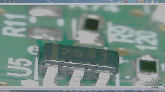
Currently in one of my design I am using UCC27531DBV mosfet driver for switching 24V supply to load.
As per truth table mention for the device, when EN and IN both pins are active LOW, OUTH shall be High Impedance state, however I found OUTH value as 7.5V.
With this my P-channel mosfet gets turned ON, however it shall not be turned on???
Below is the snap shot of the circuit diagram:
When both IN and EN pins are low, how much voltage we can expect at the OUTH pin?
When PS_EN signal is driven LOW, T12 mosfet is switched OFF, so T1 should be also OFF.
When PS_En signal is driven HIGH, and IN is still LOW, as per truth table we shall get High Impedance at the OUTH pin, but in that case alsoT1 is turned ON.
However when both IN and EN pins are driven HIGH, T1 mosfet is switched OFF - that is correct as per the truth table - and designed to work in that way.
Please explain this behaviour of the UCC27531DBV?
Best Regards,
Rajesh


