This thread has been locked.

If you have a related question, please click the "Ask a related question" button in the top right corner. The newly created question will be automatically linked to this question.

TPS630250: Internal transistor failure

Part Number: TPS630250

Hi,

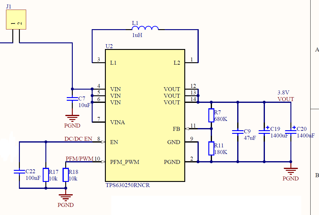
We've issue with TPS630250. After running for few hours its internal transistors fails. We can measure aprox. 20 Ohms between pins VIN and L1, L1 and GND. Converter was loaded with GPS/GSM module, static current was less than 20 mA and current peeks were up to 1.6 A.

We've replaced the part and lowered output voltage to 3.52 V by replacing R11 with 200k resistor. It fails again after 10 hours of running, but this time there is short only between L1 and GND.

It's powered by battery with voltage from 3V to 4.2V. The issue occured with fully charged battery.

Our other prototypes of same board are working well. Oldest board is running for 4 months.

Do you've any suggestions for solving the issue?

  • Hi

    What's the satisfied current and RMS current of your inductor?  And what's the level of the EN and PFM_PWM pins separately when board work well and doesn't work after several hours? Thank you!

  • Hi, Vental

    Inductor's Isat(max) = 9.8A and Irms(max) = 4.5A. EN pin is driven by MCU and there is 2.8V before and after failure. PFM_PWM pin is connected just to pull down resistor, there is 0V in both cases.

    Thank you.

  • What's the different between your old board and the new one? Just the output voltage? 

    And when you check the broken board, you need to remove the inductor and then check them to make sure where is short.

    I just think when you plug in the full charged battery, there will be a overshoot voltage and inrush current because of the parasitic inductor of the long wire and the input cap. If the overshoot is more than 7V, it will breakdown the IC. And the way to avoid this risk id to add  a TVS to GND in the input or add a snubber circuit.

    Thank you!  

  • "Our other prototypes of same board are working well" : Do you have the same layout and measurement setup on the prototypes that work well and this damaged one?

    How are you generating the pulse load?

    is the supply directly connected to the battery during the test

  • Hi,

    Sorry for late response. Input capacitor was populated with lower value than specified. We've replaced it. The board is now working correctly for seven days continuously.

    Thank you for your help.