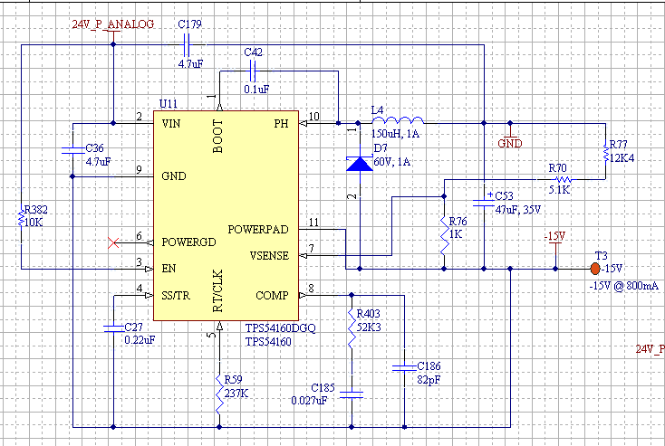
My customer asks: We are having problems using the TPS54160. We are using this part as per the app note SLVA317A to generate a negative voltage. We pretty much used the exact same setup as the app note with minor changes to the voltage divider to generate -15V instead of the -12V in the app note. What we found is very strange. On our fully populated board, the -15V does not start up, it only goes to about -900mV. Then I populated just the TPS54160 device and its require components on a blank board and it was able to generate -15V.
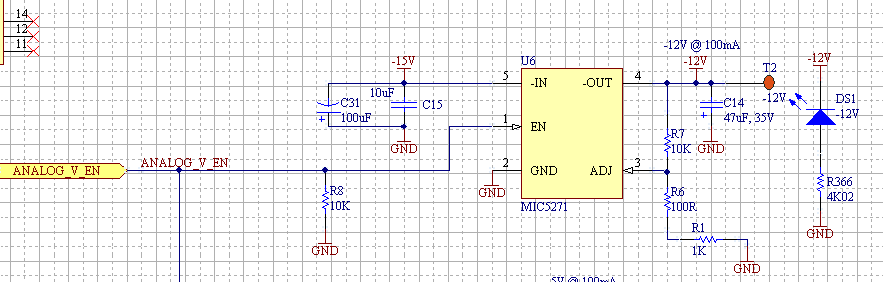
This -15V rail on our board just feeds a -12V LDO. On the fully populated board, we removed this device and the -15V does not start up. I then thought that it might be the capacitors on the input of the -12V LDO so I added these to the blank board with just the TPS54160 and the -15v still works on the blank board. I also did a quick resistance measurement on -15V rail and it measures about 12K on the fully populated board so there is not a short.
I then replaced the old TPS54160 with a new part on the fully populated board and still it does not work. Also, I removed the 10K pull up on the EN pin for all of the experiments as this was a NC pin in the app note.
Please see attached schematic pages of the -15V circuit and the -12V LDO that is powered from the -15V.
I think the problem has to do with some interaction of the -15V regulator with the other circuits on our board. Also, I would like to know if TI has used this circuitry in a multi rail system. We currently product 5V, 3.3V, 1.2V, 12V, on our design but they are not connected in any way to the -15V.