1. Why processor need multi power rail?
- Different IP cores, memory and peripherals typically have different operating voltage
- The operating voltage of each IP core may change independently to achieve best performance;
- Proper power-up and power-down sequencing are needed to guarantee the normal operation.
2. Does TPS65917-Q1 support power sequencing configuration by the user?
Power sequences are pre-programmed by OTP (one-time program) during standard production, it can't be modified in using once programmed. However, the user (through software) can enable and configure this resource independently when the power sequence completes.
3. Why do we use the multi-phase power supply?
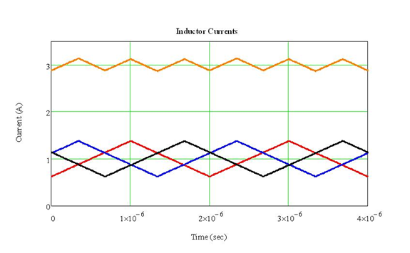
Increasing the switching frequency of a singla-phase buck converter has some benefits, such as improved dynamic response, reduced output ripple, and smaller inductor size. However, the efficiency decreases because switching losses increase with frequency. The selection of output inductor and power dissipation increasingly become an issue at higher current, especially when used in size constraint application.
To solve this dilemma, multi-phase power supply are thus developed. The idea of a multi-phase buck regulator is to put several buck regulators in parallel but have them operate in an interleaving manner. See figure below. The three-phase synchronous buck regulator has identical components for each phase, but the switching actions are 120 degrees out of phase.
A multi-phase power supply provides a method of increasing output current without sacrificing efficiency and switching frequency. Other advantages of this solution include reduced input and output capacitor RMS currents; reduced EMI filtering requirements; lower profile and decreased PCB real estate solution size; better thermal and forced convection performance; improved reliability and power stage redundancy; and easier power train component selection.
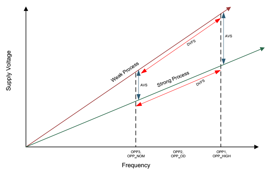
4. What is the difference between AVS (adaptive voltage scaling) and DVS (dynamic voltage scaling)?
Adaptive voltage scaling (AVS): The processor's minimum supply voltage at a specific frequency varies because of the manufacturing process variation. The minimum supply voltage results are tested on ATE during standard production and programmed onto each IC. To supply each individual processor with just enough voltage so that each processor can achieve the desired performance while minimizing power consumption, AVS is implemented to adjust PMIC output voltage based on the minimal supply voltage read from the individual IC.
Dynamic voltage frequency scaling (DVFS): In general, the application processor can achieve a better performance by increasing its operating frequency. However, the power consumption will also increase. DFVS can adjust output voltage level based upon the desired processing tasks to achieve the best performance or lowest power possible, as shown in below figure.
Dynamic voltage scaling (DVS): DVS is any output voltage scaling, which includes both AVS and DFVS.
5. What' s the purpose of the POWERGOOD function?
The POWERGOOD function is used to indicate if the outputs of the SMPS are within the acceptable range of the programmed output voltage/current. User can use POWERGOOD to report power supply condition to processor directly, this solution is easy to implement, with no programming needed.
Note that there is no dedicated pin for POWERGOOD, GPIO_6 is configured as POWERGOOD function in OTPs 0x30 and 0x32.
6. Does TPS65917-Q1 have voltage protection (over voltage/ under voltage protection)?
TPS65917-Q1 does not have dedicated voltage protection feature, some possible approaches are provided below:
- POWERGOOD function can be implemented to monitor if the output of the power supply is below the POWERGOOD threshold.
- The device offers 12-Bit Sigma-Delta General-Purpose ADC (GPADC), which can be used to monitor an output voltage. This paired with the interrupt will allow the processor to take the appropriate actions to address either overvoltage or undervoltage condition.
- External voltage monitor can also be applied to monitor the output voltage.
7. How to manage EMI while 5 SMPS operating at the same time?
A PLL is used to create 5 clock signals for 5 SMPS with a different phase, which contributes to reducing EMI. Noise may be overlaid (added together) if 5 SMPS operate at the same frequency. In addition, a dithering of SMPS clock can be enabled to minimize EMI.