This thread has been locked.

If you have a related question, please click the "Ask a related question" button in the top right corner. The newly created question will be automatically linked to this question.

LP5521: Trigger I/O and clock question

Part Number: LP5521

Hello,

         Here’re few design questions would like to check.


Customer need a simple control by CPU to notice this DRV for LED action.

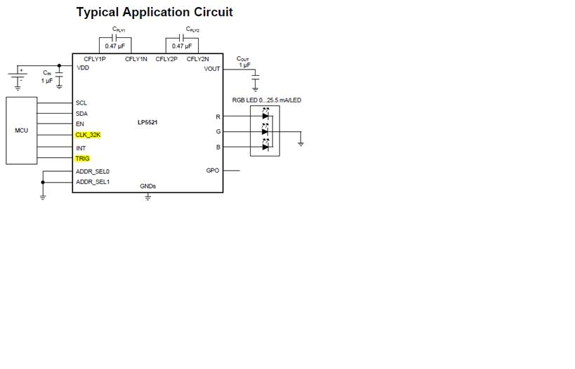
So the INT is set NC, but I would like to check CLK_32K and TRIG.


Spec: A trigger I/O and 32-kHz clock input allow synchronization between multiple devices.


What’s the detail behavior of TRIG pin? And is the CLK 32Hz really necessary when I use just 1 driver?
My setting now is TRIG =GND, CLK=32KHz input. Thank you.

BR

Patrick

  • Hi Patrick,
    If you have only has only one LP5521, the clk is not necessary. Just connect to GND. For the trigger pin, connect GND when not used. Please refer the detail as below in the datasheet.

    The TRIG pin can function as an external trigger input or output. External trigger signal is active low; that is, when trigger is sent or received the pin is pulled to GND. TRIG is an open-drain pin and external pullup resistor is needed for trigger line. External trigger input signal must be at least two 32-kHz clock cycles long to be recognized. Trigger output signal is three 32-kHz clock cycles long. If TRIG pin is not used on application, connected the TRIG pin to GND to prevent floating of this pin and extra current consumption.
    Any other question please let me know.
    Thanks!
    Summer