


Other Parts Discussed in Thread: BQ500212AEVM-550,
Hello Guys,
i have some trouble with a selfmade design of the bq51025 receiver working with a bq500212AEVM-550 transmitter! The EVM-Module works normally with the appropriate bq51013AEVM-764. VRECT reached 8-10V an the output raised up to 5V.
For the selfmade bq51025 (designed like the appropriate RX-evm) the VRECT-Voltage reached the treshold, but than fluctuated from 8 to 15V. After communication of RX and TX, the TX moves also to power transfer phase for up to 50ms. After this VRECT will not drop out of 5.2V, but rather ~13V. This reaction is independently from the communication current limit (disabled or enabled)! I see that the ss-, id- and config-packet are very noisy, but i have placed some filter capacitors (2x 22uF X5R, 1x 100nF X7R like evm) to minimize the ripple! The Capacitors on the Antenna Out Circiut are C0G/ NP0-type with the dimensions of the evm! The Divider on the Feedback-Pin (VI-REG, VO-REG) operates correctly! If I change the dimensions, the voltage on the output switches to 7V!
In the troubleshooting report it is noted, that such reactions could be initiated by noises on the communication lines, but the filter caps are used like the evm! Differences between the selfmade design and the evm and therefore reasons for the dysfunction could be the following aspects:
- using of only one microvia for the RECT-balls from the IC (in the datasheet)
- the filter capacitors for RECT are not close enough to the IC (~11mm)
- using fixed resistors with a value of 500 Ohms and no variable resistors on the ILIM-pin
- the output (OUT) is routed about vias directly to a separate inner layer
What could be mainly responsible for the effect?
Thank you in advance for answers!
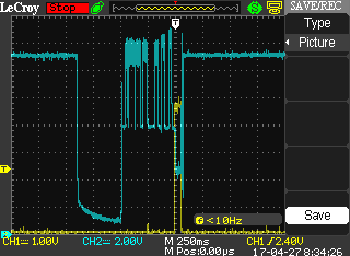
Ch1: OUT
Ch2: RECT

