This thread has been locked.

If you have a related question, please click the "Ask a related question" button in the top right corner. The newly created question will be automatically linked to this question.

LM5106: Stepper motor weird current output

Part Number: LM5106
Other Parts Discussed in Thread: INA240

Hi guys 

Recently we developing a new stepper motor driver using LM5106 and Mosfet H bridge configuration. I have to mention we have to lunch the new product by July so any help will be appreciated.

The issue is I have wired current output at speeds higher than 420 RPM above. Please have a look at the following picture.

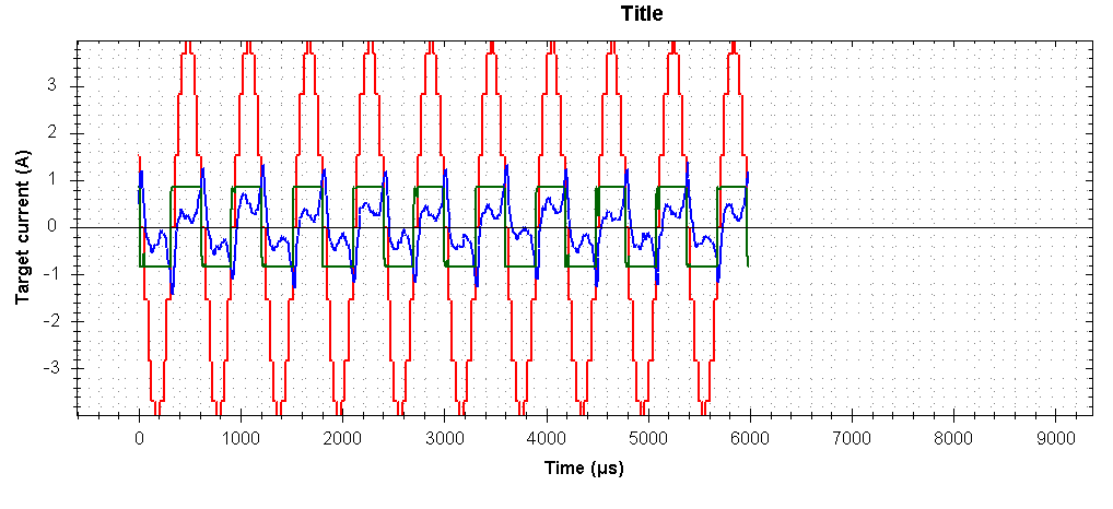
 the Red line is our micrsoteping output which feeds to the PID refrence, the blue line is current output out of shunt resistor. green line is output of PWM. PWM 1 means 100% in forward direction and -1 means 100% in backward direction. as you can see my PWM reach to maximum but still the desire current is not being achieved. I know this is due to back EMF stuff, still the shape is not very logical to me and I m not able to explain it.

however at lower 300RPM I get something way more meaningful please have a look at the following picture.

although the feadback current due to inductance is messed up but still is acceptable.

if i go for higher RPM  the graph  get worst. the following graph catured at 600rpm

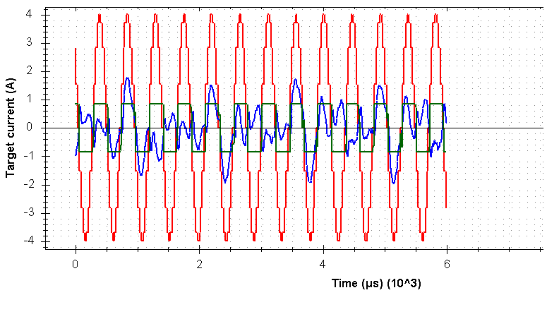
 If I go a bit higher RPM than this the motor stall.

So I wonder if anyone could help to explain the graphs , and even it would be better if someone could help to solve this problem. 

For your info

  • the Vbus voltage is 24 volt --> I cant change power suplly source due to cusstomer specefication. however I have tested the 48 volt which obviously give much more decent output due to better ability to overcom BackEMF voltage
  • the motor inductance is 2.1mh
  • the resistance is 1.1 ohm
  • the motor rated current is 4.0 A/phase

  • Hi, Nima

    Thanks for your interest in TI here. I've contacted the appropriate product group. You should hear from them soon.

    Regards,
    Yunsheng
  • Nima,

    I am an applications engineer for the LM5106 and will be working with you on this item. To begin with, I would like to get a better understanding of the application:

    - Where in the circuit is the shunt located?
    - Are the plots above actual collected data or a tool simulation?
    - What do the waveforms for the LM5106 outputs look like? Do you suspect the LM5106 is the culprit?
    - A partial schematic showing the part of the circuit with the driver, FETs, shunt, and motor would be quite useful.
    - What value of RDT is being used to set the dead time? Have you confirmed that this dead time setting meets application needs through the RPM range?

    Hopefully we can resolve your issues and help your team meet your deadline.

    Regards,

    - Daniel
  • Hi

    - Where in the circuit is the shunt located?
    we use INA240 inline with motor to collect the current information . the good thing is that INA240 is bidirectional current sense IC. therefore I don't have low side current issue stuff.

    - Are the plots above actual collected data or a tool simulation?
    Actually we created a software which work as oscilloscope . every time we trigger the software it will provide us the last 2000 samples from the reference and feedback and output of current loop. If you need any other imortant inforamtion I could still add to software. so please let me know if you need any other readings .

    - What do the waveforms for the LM5106 outputs look like? Do you suspect the LM5106 is the culprit?
    LM5106 is perfect, no issue. my PWM after LM5106 also clear . definetly the issue is not from LM5106. Most probably our issue comes from some mistake in the way we control the motor on the algoritm side and etc.


    - A partial schematic showing the part of the circuit with the driver, FETs, shunt, and motor would be quite useful.
    I wonder if you could provide me your email address or something. since this is a company project. not very convenient to disclose the schematics in public.

    - What value of RDT is being used to set the dead time? Have you confirmed that this dead time setting meets application needs through the RPM range?
    at this moment I dont reameber the value but I m sure is not dead time issue. the LM5106 is working perfectly so far at 20khz. at higher frequency LM5106 under 4 amp will burn and I have many issues with LM5106 at any speed higher than 25KHZ but that one I will most probably will create another page for it.
  • Nima,

    Thank you for providing further details. I have sent you an e2e private message/friend request so you can securely share the schematic with me.

    One possibility to consider is an issue with the PID controller sample rate vs the system bandwidth if you are using digital control. Could it be that the PID loop is not running fast enough to keep up with the plant? What is the controller being used?

    I will take a look at the schematics once I receive them and let you know if I see anything that could help. Please understand that I may not be able to debug issues that are not related to the TI device (s).

    Regards,

    - Daniel
  • Hi Nima,

    Thanks for considering TI part for any and all of your needs.

    Would it be possible for you to share the schematic as much as possible?

    Regards,

    Ritesh

  • Hi Daniel

    Actually we run PID at the same speed rate as PWM frequency which is 25KHZ. And we have tried higher speed PID and PWMs . Up to 100khz which is quite high. Still the result is same and no we achieve no improvement.

    The PID get saturated in high speeds and it forces the PWM to 100% duty cycle. the response is very fast which is correct but the current output cannot even get close to to request reference, not reaching to refrense is not an issue but the shape of current get disorted , and this shape distortion is an issue . In my humble opinion, this is not PID response time issue. I have to mention we have competitor which we test bench our product with at the same speed they fully reach to 100% pwm exactly like us. but when we measure their current output with our very expensive accurate current probe their output is really meaningful oppose of us ,our current output at full speed and under 100% PWM duty cycle is really messed up.

    Our original PWM was centered aligned. but yesterday we tried a PWM signal which is exactly look like slow decay PWMs inspired by TI reference designs. As a result the current output become more stable, but after some time hardware get unstable and started to burn . we tested the new pwm few times, one time INA240 burns another time LM5106 burns, another Time one of the mosfet burns. still testing the Slow decay PWM signal once I get better result I will update you again regarding it.

    But still my competitor runs a centered aligned 25KHZ pwm and they set PWM duty to 100% and they have very meaningfull current output and we don't .I really dont know where the problem comes from.

    Still thanks for you prompt reply and I hope you could guide us through this mess :D .
  • Nima,

    I received the schematic via private message, and I have reviewed it with Ritesh. We did not identify any issues related to the LM5106 or the power MOSFET stages. The schematic I received did not show any bulk capacitance for the power supply of the H-bridges, but I imagine they are shown somewhere else in the full schematic document. Insufficient bypassing could be one reason for not being able to draw enough current when running at higher RPM

    Our suspicion is that you may be experiencing a control issue. Some items to consider:

    - Check scaling of any feedback values and ensure nothing is clamped

    - In PID loop check if the constants and multipliers are as they need to be

    - Generally switching frequency and loop bandwidth are not the same - have you tried speeding up the PID with respect to the PWM?

    - Does the current measured with your custom software instrument match what you measure with the accurate current probe?

    Since the issue does not seem to be related to the TI device, we offer the ideas above in good faith, but we may not be able to further debug the system issues.

    Best of luck, and please do let us know if you find out what the problem is, as it will benefit the entire e2e community.

    Regards,

    - Daniel

  • Hi Daniel

    for the question you asked for control side I think I m quite ok. but regarding bulk cap I m not sure. in the second message which I send you today as you can see we use only one capacitor at the 24 volt input which is 330uf/50V. I frighten as you said it might not be enough. But PWM output is clean. might the problem cause by this capacitor?
  • Try adding 100nF - 470nF capacitance to each half-bridge using one or multiple ceramic caps. Placement should be as close as possible to the FETs. Try to make the current loop as small as possible for current to flow out of the cap, into the high-side drain, and out of the low-side source back to the cap/GND. A second cap (or set of caps) in the 1uF - 10uF range placed next in distance from the half-bridge

    You can try out the effects of these mods by first adding the first set of caps (100's of nF range) to one half-bridge and test it. If you notice positive effect, then you can add some more caps, and eventually apply the same to the other half-bridges.

    The large 330uF cap is good for bulk capacitance for the board, but the immediate turn-on current for the MOSFETs needs to be able to be supplied quickly. That is the function covered by the additional, localized, capacitors suggested above.

    Please give this a try and let us know how it goes.

    - Daniel