Hi All,
SLUA749A–July 2015–Revised May 2016 - bq769x0 Family Top 10 Design Considerations states, at the top of Page 22:
"If VC0 is connected on the board, it will not vary significantly from VSS, but the parasitic effect will be included in the bottom cell measurement and VC1 may need protection, see Figure 23."
We do connect VC0 to Vss on the board, both connected close to the kelvin connection to Rsns for SRN. Figure 23 does not recommend a protection method, I'm curious to know what TI would recommend.
We're seeing sporadic damage to VC1 and/or VC2 during the short circuit test. We're using a 7S6P battery constructed with NCR18650B cells. The short circuit current is around 200A. Short neat battery wiring reduces the problem but does not eliminate it. 7S6P batteries are on the large side.
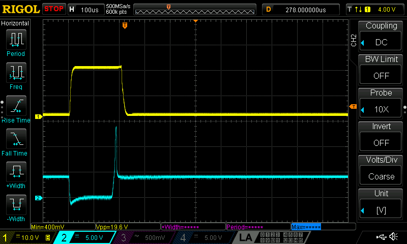
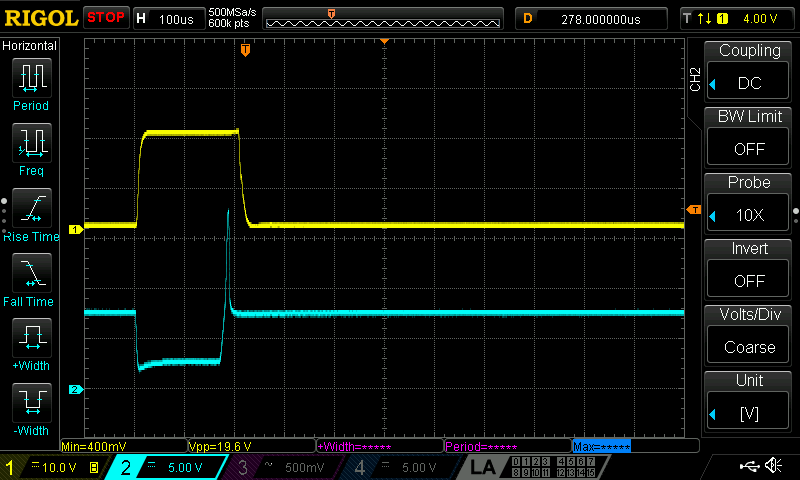
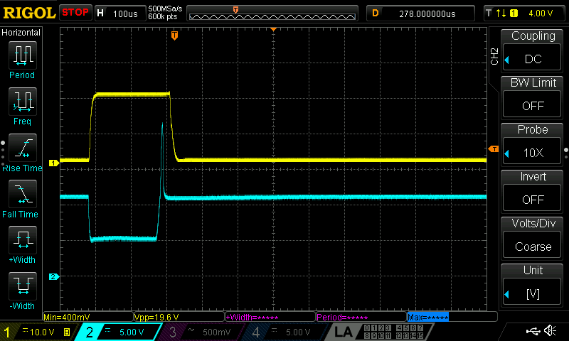
I've attached some scope traces (taken with neat battery wiring) where the upper (yellow) trace is the short circuit current measured with a clamp on current probe and the scaling is 1mV/10mA or 100A per division. The bottom trace is the cell voltage on the input to the PCB, not the actual pins on the bq76930, so there will be some attenuation of the transients but they are larger than expected. For VC3 and above, the transient does not exceed the absolute input voltage rating of (n x 7.2v). The 9V differential rating is exceeded by the transient but not by the voltage sag under load. The voltage at VC1 does drop to around -0.2V, we've not seen it exceed -0.3V.
Using zener diodes seems difficult considering that during balancing the differential cell voltage could be almost double the normal maximum cell voltage of 4.15V (higher at end of charge). What would TI recommend for this case?
BT1
BT2
BT3
Thanks for the Help!


