This thread has been locked.

If you have a related question, please click the "Ask a related question" button in the top right corner. The newly created question will be automatically linked to this question.

Issues with BQ27500

Other Parts Discussed in Thread: BQ27500, BQ27500-V130, BQ27500-V120, BQ27510-G2

Hi,

   We are using a BQ27500 monitor chip and we have with us a golden image file supplied by TI for our batteries.

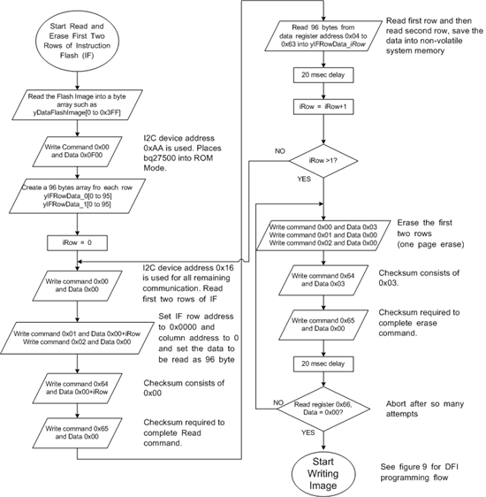
   We have followed slu449d.pdf for programming the golden image to the chip.

   We try to program the BQ27500 chip  and are unable to access any register access with address 0x55

   after we program the chip in ROM Mode.

 The following 5 steps are successful. I2c writes DONT report any errors.

1) Enter ROM Mode (I2C Address is 0x55)

2) Copy First 2 rows of instruction flash contents and Erase 2 rows of Instruction Flash. (I2C Address is 0x0B)

3) Writing Image - T(Also the DFI Checksum matches with Read Back Checksum on the chip) (I2C Address is 0x0B)

4) Reprogram the First 2 rows of the instruction flash (I2C Address is 0x0B)

5) Exit ROM Mode and Write Bytes 0x64 = 0x0F and 0x65 = 0x00 are successful.  (I2C Address is 0x0B)

The i2c writes dont report any errors.

The issues is the chip never exits out of ROM Mode. Any reads/writes to 0x55 addresss returns -5.

What could be the issue?

Also, If i omit the Step 1 (Enter ROM Mode) - I can program the image again and again without any issue.

but unable to come out of the rom mode.


I suspect that the BQ chip is unable to exit the ROM Mode for some reason.

What are the steps to put the chip back into a default state?


Please advice.


Thanks and Regards,

Sriram V.


  • Sriram,

    The first thing to check is to make sure that each of the command sequences you write is actually being executed.  After you write the checksum (I2C Registers 0x65 and 0x64), the command should execute.  If there is some error in execution, these registers will be nonzero. Since you are reading the checksum correctly, this is probably not an issue during your dataflash-writing process.

    Try checking this register (0x66) after you issue the command to execute firmware.

    I wasn't able to tell from your question: are you writing 0x0F to address 0x00 before you write the checksum (registers 0x64 and 0x65) when you are trying to exit ROM mode?


    Finally, a few general notes:

    1. Have you tried programming the default DFI image for the part that you are using?

    2. Check the firmware revision that the DFI image was created for and which firmware version you are programming.  For the bq27500, a DFI created for the V1.20 Firmware will NOT work on a bq27500 programmed with the V1.30 firmware.

    Let me know if this helps,

    Charles

  • Charles,

     I am following the flowchart http://focus.tij.co.jp/jp/lit/an/slua449d/slua449d.pdf exactly. (Pages 8 to 11)

     Before i exit the ROM mode i write the following as given in the flowchart:

     Command 0x00, Data 0x0F

     Command 0x64, Data 0x0F

     Command 0x65, Data 0x00

     Send RESET on 0x55 === FAILS

    Delay(1s)

     Send IT_ENABLE on 0x55 === FAILS

    Also, Can you please let me know which command i am supposed to run to execute the firmware?

    Are there any specific command to run in ROM Mode.

    I do a RESET and IT_ENABLE  ( 0x0041 and 0x0021) after exiting from the above commands.


     I use  BQ27500DRZT  Chip, Could you please send me the default instruction flash data and the DFI data. I would like to check if i could recover.

    I only have a DFI file with me. Is it possible to check the firmware version for which the dfi file was generated. Which byte offsets am i supposed to tell the firmware version.


    Thank you.


    Regards,

    sriram


  • The command you mention: writing 0x0F to address 0x00 and writing the checksum should send the device to firmware. 

    One thing you can do in ROM mode is to read register 0x66 after your device fails to re-enter firmware mode.  This register will contain any error codes.(0x00 means no error).  I have attached the DFI file to this post.  The default DFI files are also contained in the bqEASY directory (plugins/device defaults) when you install our Evaluation software. 

    If you send me your DFI, I will check which firmware it is designed to run on.

    Thanks,

    Charles

    bq27500_1_30.dfi
  • Hi Charles,

    I am working on TI’s Bq27500-v130 gas gauge for a customer and have developed an issue that very closely mimics this thread.  I am attempting to re-flash the gas gauge with a custom Golden DFI file using directions from the SLA559d Applications Report.  However somehow I have gone astray.  The chip will no longer leave ROM mode. 

    At the end of the procedure I am writing:

    0x00, 0x0F

    0x64, 0x0F

    0x65, 0x00

    and then trying to reset the chip by writing to the 0x55 address and the i2c write is failing.  I was wondering if you could post the list of errors that accompany the 0x66 register read.  My hope was that the error codes would let me figure out where I am going awry.

    Thanks!

    -Colin

  • I was wondering if anyone could help with my previous post.  

    Thanks.

    Colin

    Colin Foe-Parker // software engineer

    Logic PD /// engineering design services

    5 Clock Tower Place. Suite 400
    Maynard, MA 01754

  • Do you mean SLUA449d instead of SLUA559d?

    Is your problem at the last step of Figure 10?  After this step it should be responding to I2C traffic at the usual firmware I2C address (0xAA).

    There is no read of register 0x66 for this final step.  Can you please explain your issue another way?

    If you somehow corrupted the dataflash or didn't successfully program everything correctly then the IC will remain in ROM mode and will not execute the FW.  That could be what is happening to you if it's not going to Firmware mode.  That's why the flow charts have you go back and start again if 0x66 doesn't return 00.

    By the way, some customers have run into problems on Figure 8 where they erase the wrong two rows, so we are about to update SLUA449D (next version should be E) Figure 8 with the flowchart below.  The sixth shape from the end is adding writes of 0x00 to addresses 0x01 and 0x02 in case they somehow got changed elsewhere.


  • Hi dMax,

    Thanks for the help.  Yes, I did mean SLUA449d.  I mistakenly hit the wrong number on the keypad

    Yes, I am having troubles at the end of figure 10.  The gas gauge will not leave the ROM programming mode.  I have created a golden DFI image and tried following the entire flow chart from SLUA449d.  At the end of Figure 10 I am writing:

    0x00, 0x0f 

    0x64 0x0F

    0x65 0x00

    Which I believe should make the chip leave ROM mode and re-enter flash mode.  However, afterward, when I try communicating with i2c address 0xAA the device fails to respond and when I communicate with the ROM i2c address it responds.  Which is glaringly telling me that I have screwed something up.  

    I will update my process to mimic the updated figure 8.  However, if I have corrupted my data flash is it possible to recover from this situation or is the gas gauge now bricked?  (The test IC that I am using has been power cycled since I last tried programming it)  

    I referenced reading register 0x66 because of Charles Herder's suggestion earlier in the thread, "One thing you can do in ROM mode is to read register 0x66 after your device fails to re-enter firmware mode.  This register will contain any error codes.(0x00 means no error)."  This statement made me think that there must be a list of errors that could be identified by register 0x66.

    Thanks for your help.

    -Colin


  • If you didn't successfully finish programming the golden file into dataflash then it should stay in ROM mode even if you POR.  It should still be in ROM mode for you and you can retry programming it using the updated flow assuming it still responds to address 0x16.

    Another thing to confirm is that you are programming a DFI that is compatible with the FW version loaded on the IC.  For example, if you made a golden file for bq27500-V130, do NOT program it onto an IC with another FW version, like bq27500-V120 or bq27510-G2, for example.  In most cases it will brick the IC, but it's theoretically possible that it might make it stay in ROM mode or even execute FW and look mostly normal to the casual observer.

    So...

    - Does every step of your code leading up to the end of Figure 10 get successful results (0x00 in 0x62)?

    - Are you sure your DFI file and IC FW versions match?

  • Hi dMax,

    Thanks again for your help.  

    I think you might have pointed me right to my issue.  I used the BQ27500EVM kit to create the golden image and when I look at the bottom of the BQ Gas Gauge Eval Software it says "Device: 500, Ver: 1.08"  I used this golden image and programmed it into my BQ27500 v130 chip on my product.  That being said, am I now SOL?  Or is there a way to see if I can recover from this situation if I don't think I have ever successfully exited ROM mode?

    In hope that I might not be in a bricked situation,  I discovered that I am getting a response of 0x04 from register 0x66 after I write the first 96 bytes of data in Figure 10.  (Bottom block of the first column of instructions)  I have been using this gas gauge for development so it is very possible that the yIFRowData_iRow[0->95] was corrupted earlier.  Does this data have an internal validity check in the IC to make sure the 192 bytes that are being sent from the host application makes sense?  

    Sooo....

    1.) Am I SOL or is there a chance that I can recover from this situation?

    2.) What does 0x04 mean when I read register 0x66 in figure 10?

    Thanks!

    -Colin

  • If it is responding in ROM mode (ACKing the ROM I2C address of 0x16) then you can still recover.  Since you didn't complete the process and stopped on the error the gauge will never try to run FW.

    You have two paths now:

    a) Use EVSW to upgrade your EVM to bq27500-V130 by downloading the SENC from the product folder and following the instructions on page 5 of http://www.ti.com/litv/pdf/slua453a.  You can skip step 5 since you are already in ROM mode.  Once this is done you can retry your DFFS.

    b) Alternatively you can try using the bqfs file which will program the dataflash AND instruction flash, thereby upgrading it to bq27500-V130 and programming your custom dataflash at the same time.

  • Thanks dMax.  

    I successfully updated my eval kit to the 1.30 version firmware.

    That being said, I think a description of my setup would be beneficial.  I have the BQ27500EVM that I used to create the golden image for my application's battery model.  This EVM was initially version 1.08 but I have now updated it to 1.30.  I also have a custom application board that has two BQ27500v130 gas gauges on it.  This custom board also has a Atxmega64d3 MCU on it.  The MCU is needs to re-program the gas-gauges when we go to production so I am developing the code to program the golden image.  The custom board does not expose it's i2c bus and there is some other bus complexity that removes BQ Evaluation software from a manufacturing flash procedure.

    When I try to re-program the BQ27500v130 gas gauges on the custom board with the default v130 (32 by 32 byte array) golden image from the BQ Evaluation software it isn't leaving the final 192 byte interface flash write procedure.  (Figure 10) After I write the first 96 byte checksum value and read register 0x66 the returned value is always 0x04.  I have had a co-worker look through the MCU code and we both think that it matches the flowchart in SLUA449d.  It is very possible that in my development I have somehow corrupted the yIFRowData[2][96] data.  Could corrupted data explain the 0x04 on the checksum?  

    In re-cap:

    • What does an error message of 0x04 mean after I write the checksum in figure 10?
    • Could a corrupted yIFRowData explain the checksum issues I am seeing?  If so, could you provide an example array that would we accepted.

    Thank you again for all your help.

    -Colin

  • Hi dMax,

    Thanks again for all your help.  I think I am getting really close.  If you could please give me a little more help I would appreciate it.

    -Colin

  • Hi Niloc2004,

    I have the same experience that you described with the 0x04 checksum value returned after writing the IF.  I am writing custom code to do the DFI program on these bq's.  When I write 32 byte blocks of DFI data it was fine, but I tried to load the IF 96 byte array with a single command and that resulted in non-zero checksum.  Checking the flash space revealed that the data did not actually program, which makes sense because you need 0 checksum value for the data to transfer from buffer to flash.  However, when I send the 96 bytes of IF in small blocks of less than 32 bytes it seems to work.

    I don't think your data is corrupted because I saved my yIFRowData to a file during first read to make sure I always have the original and used this data when I did the above.

  • Hi Niloc2004,
    Writing the IF in small blocks of data, what command did you use?
    Also, will you be able to exit from ROM Mode?
  • Hi Sime,

    I'm sorry but I'm not going to be able to help you on this. My last post was in 2012 and I no longer have access to the customer's project. Good luck finding your issue!

    -Colin
  • Hi Martin,
    I tried small blocks of 32bytes for writing yIFRowData, still doesn't work. Still got 0x04 from 0x66.


    Also, after IF Erase (Page 8) tried to read the IF 96 bytes , I got series of "FF FF 3Fs"...in both rows. Is this correct?

    Also compared the IF write data vs IF read data, every 3rd data is wrong.

    For example:
    Write: FF EA 76
    Read: FF EA 36

    Every third being written data is AND with 3F.
    Now how to get rid of 3Fs?
  • Notes to consider:
    For IF Data, the maximum value on every third data on both IF Rows is 3F...

    Writing the exact value being read from Page 8 of SLUA449 or SLUA504a will resolve the issue on 0x04 on Register 0x66 after IF Data Write
    (Page 11).


    BUT, I encountered another issue -- after exiting from ROM Mode without any error, the device cannot be accessible anymore...

    Need some experts here on how to resolve this issue,,,,
  • Issue resolved....

    In writing the IF Data and DFI Data, it should NOT be in little endian format.