This thread has been locked.

If you have a related question, please click the "Ask a related question" button in the top right corner. The newly created question will be automatically linked to this question.

BQ25570: Li-ion battery not charging

Part Number: BQ25570

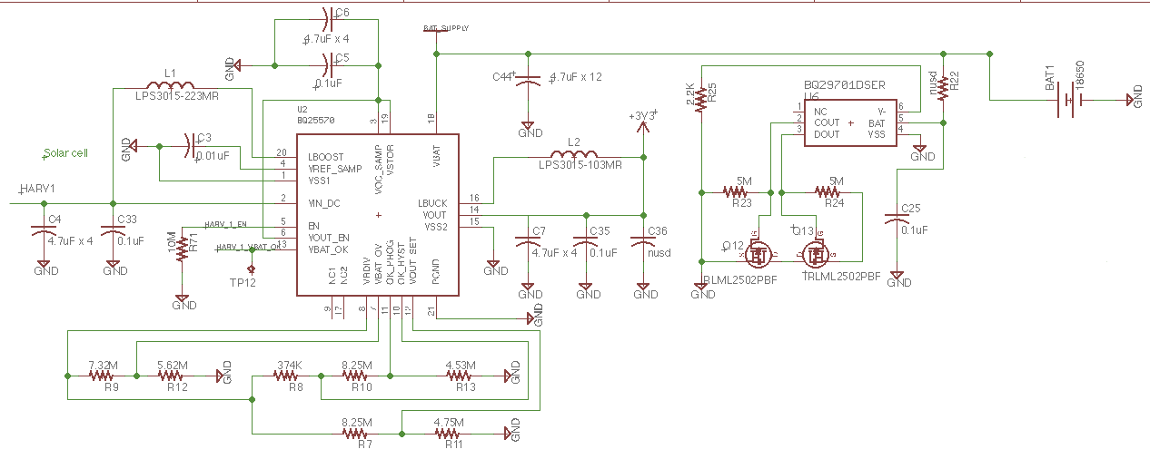
I create a PCB with the attached schematic.  I tried to follow the application in the datasheet.  I added the lithium-ion battery protection circuit but this should not affect the charging of the battery.  I am using a couple 3V solar cells from powerfilm solar (part number LL3-37) on the Vin-DC pin.   I hve ground the EN pin on the PCB.  There is no MCU control to this circuit.  Finally, the Lithium battery is currently at 2.049V and I am attempting to charge it without a load on Vout.  

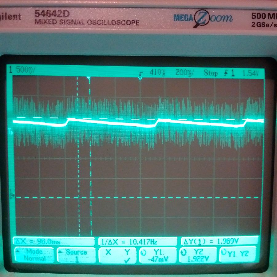
I have tried both a single solar cell and 2 solar cells in parellel.  The open circuit voltage is 3.0V.  However, when I connect the solar cells to the BG25570 on the Vin-DC the in circuit voltage drops to 0.432V. .... not 80% of 3 V as the datasheet says it should.

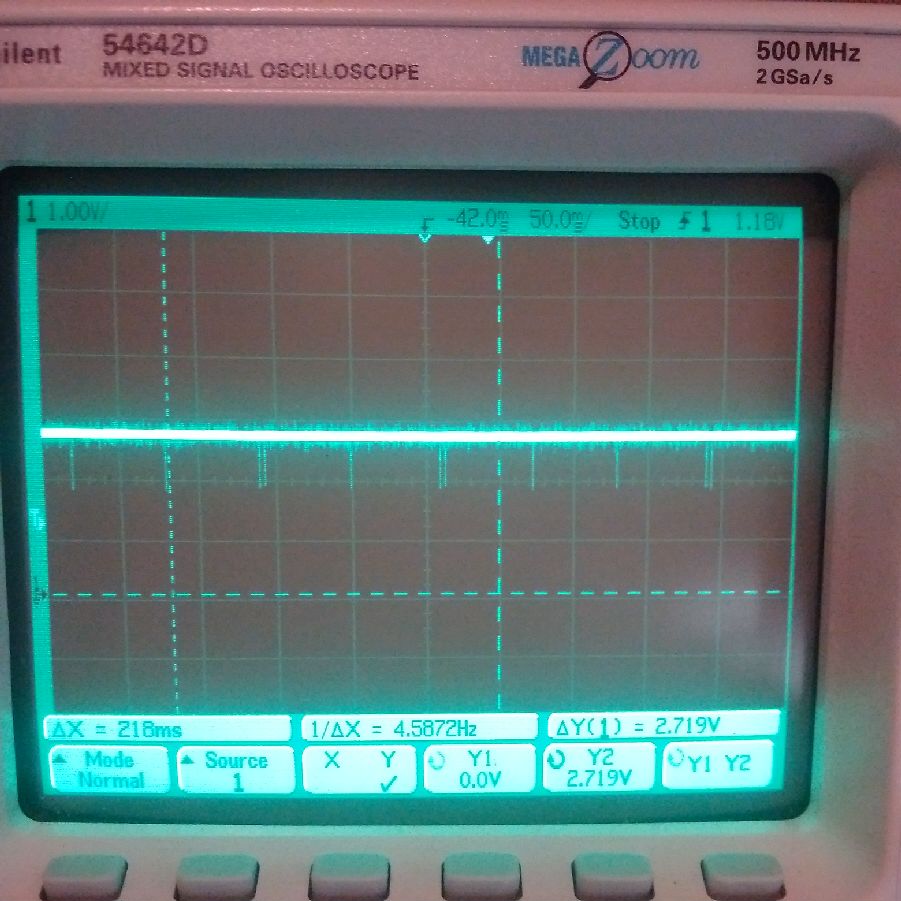
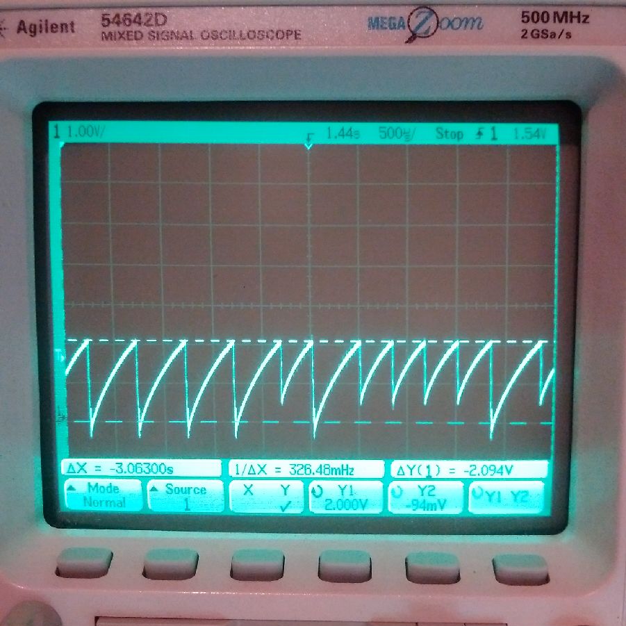
When I add light to the solar cell the voltage on the battery is slowing increasing about 0.001mV every 15 seconds so it is doing something but it never gets up above 2.1V.   Clearly the 3.7V lithium battery is not charging. 

I am sure it has something to do with the configuration of the IC.  The in circuit voltage on the Vin-DC does not increase when I use 2 cells or 1 cell.  The voltage on the solar panels is always 0.4 something volts not 80% of the 3V open circuit voltage.

Any idea what I am missing.   Attached is the schematic.

Thanks,

  • Hi Chris,

    Is VSTOR sitting at your battery voltage? This will determine if the PFET is on.

    What is your VOUT voltage at?

    Do you know what the equivalent capacitance of your battery is? There should be at least 100uF of equivalent capacitance from VBAT to VSS. You could try adding come capcaitance on VBAT.

    Also, can you try only charging the battery or cap without the BQ29701? This way we can rule out that it is not causing any issues. It looks like all you would need to do is depop R22.

    -Joe
  • Hello Joe,

    Thanks for your help. I made a couple of changes as you suggested.
    1. VSTOR is the same voltage as the battery.
    2. I actually do have a 100uF added to the battery....sorry not in the schematic. ( it was a troubleshooting mode and forgot to add it.)
    3. I also increaased C6 from 4.7uF to 26.7uF ( added a 22uf cap)
    4. I removed R 22 so disconnecting the BQ29701.

    This last change created some improvement.

    1. The battery can now be charged above 2.6V.
    2. The in circuit voltage on the solar panel is now 1.43V, which is very close to 50% of the solar panel open circuit voltage of 2.99V.

    So maybe there are two issues.

    1. The BQ29701 is loading the battery.
    2. It appears the BQ25570 is configured for 50% of the source open circuit voltage. Of course it is not VCC_SAMP is connected to VSTOR so I should see 80%.


    Any thoughts on these two items? How can I fix these?

    Thanks,


    Chris
  • Chris,

    What kind of capacitor are you using on VREF_SAMP pin? Leakage on the VREF_SAMP pin can cause problems with regulating VIN. It is recommended to use a low leakage X7R or COG low leakage capacitor.

    You may also want to try increasing your input capcaitance. It could be that your input is having troubel staying at the 80% set point. Have you connected this up to a scope yet? You could monitor the input and see if it ever spikes to the 80% set point and then sag down to 50%.

    Also, you mentioned the EN pin is grounded. Does that mean the blue line in the schematic is ground? If so, it looks like the VBAT_OK pin is grounded as well. This pin should be left floating if not being used. Grounding it may be providing a leakage path.

    -Joe
  • That is a good point.  I am using a bunch of different types of capacitors,   X5R, X7R and COG.  I changed all of the capacitors so they are all X7R.  Some of the values had to be created using many caps.  I have updated the schematic to reflect what I did.  Also EN is grounded and VBAT_OK is floating.

    I have ordered some more capacitors, which should arrive tomorrow. So I can swap out some of the caps where I had to use many.

    I also took a screen shot of my oscilliscope measurement of the input voltage.  See below.

    The screen shot shows the voltage is not steady at 2.656V but is pulsing.  I need to increase the capacitance I think.  I ordered some 47uF and 22uF caps of X7R.  I will try them tomorrow.

  • Hello Joe,

    I received my capacitors and did the following changes.

    C4 is a 47uF X7R  ( GRM32ER71A476ME15L)

    C44 is 94uF ( 2 of 47uF X7R)  ( GRM32ER71A476ME15L)

    The input voltage on my scope shows the following.

    When I increase the capacitance of C4 to 96uF  the voltage is steady at 0.3V with no ripple.   The added capacitance kills the waveform so I removed it.   C4 = 47uF.

    The voltage on the battery is charging.  It is increasing 0.001v every 7-8 seconds in the range of 1.579v to 1.580v range.

    According to the datasheet, I believe the input voltage should be somewhere around 2.4v measured by a volt meter.  I do not know what it should look like with a scope.  Is it suppose to have this waveform on it?  A changing cap waveform would be reasonable.    What should the waveform on the input look like?

    I am going to let this run overnight an see if the battery charges.

    Thanks,

    Chris

  • This is not what is expected on the input. The input voltage should stay steady at the MPPT set point and then pulse to the open circuit voltage every 16s for a short sampling period. Refer to figure 27 on page 25 of the datasheet.

    I think too many things are being changed at once. If you could set it up in a very basic set up, similar to the example in the datasheet, we can slowly step through and debug.

    C4= 4.7uF, C6=4.7uF. Keep R22 depopulated, and remove the battery.

    I would be interested to see what VIN, VSTOR, and VBAT waveforms look like with the solar panel supplying power. Then again with a DC power supply.

    -Joe
  • Hello Joe,

    I did the following.  Changed C4 and C6 to 4.7uF and removed the battery.  The battery line now as 2 47uF X7R caps on it.   I did some measurements the first three photos are with the solar cell from PowerFilm  ( LL3-37)  -->   http://www.powerfilmsolar.com/products/?ll337&show=product&productID=284197&productCategoryIDs=6573

    scope measurement of Vin with Solar cell

    Scope measurement of VSTOR  with Solar cell

    Scope Measurement of VBAT with Solar cell

    I repeated the same measurements using a bench top power supply ( GW INSTEK  GPS-3030DD)

    Scope Measurement of VIN with power supply

    Scope Measurement of VSTOR with power supply


    Scope Measurement of VBAT with power supply

    It appears that the solar cell is loading the circuit somehow.  What do you think?

    Thanks,

    Chris

  • Hi Chris,

    What your waveforms are telling me is that the IC is stuck in cold start mode when the solar panel is on the input. This can be seen from your VSTOR waveform. It looks to me that every 220ms or so the VSTOR voltage drops below the VSTROR(CHGEN) threshold of ~1.7V. This can cause cold start to restart.

    Also, since VSTOR is reaching 2.7V, which is above VBAT_UV of 1.95V, the internal PFET connecting VBAT and VSTOR is turning on. This then turns back off when VSTOR dips. This is why you see a voltage on VBAT That is not equal to VSTOR and definitely not your set VBAT_OV voltage of 4.2V, which can be seen in yoiur waveform of VBAT with the solar panel.

    Are you loading VSTOR at all? I know your schematic doesn't show it, I just want to double check. Loading on VSTOR can cause dips.

    I suggest increasing the capacitance on VSTOR so it doesn't drop below 1.7V. Check again, VSTOR and VBAT waveforms.

    -Joe
  • Hello Joe,

    I double checked the circuit and VSTOR is connected to VOC_SAMP and VOUT_EN.

    C5 is 0.1uF  x7R.

    C6 was 4.7uF x 4 caps.

    There is nothing else on this net.

    I changed the value of C6 to see what happens and as you suggested, increasing the value has helped.  I replace C6 with a single 47uF cap (X7R) and measured, Vin, VSTOR and VBAT again.

    Vin peeks at 2.3V with noise on the line up to 2.8V.

    VSTOR has a waveform that moves from 1.79V to 1.969V.

    VBAT is steady at 1.67V.

    1.67V is approximately 72% of Vin.

    I couple of points.

    1. VSTOR is higher than VBAT   VBAT only has a 47uF cap on it.  There is no battery.

    2. If VBAT is at 1.67V  this will not charge a 3.7V battery.

    3. VSTOR is 77% of Vin....which is close to 80%  but this does not really help if I cannot charge a battery.

    The solar cell open circuit voltage is 2.7V dc.

    Here are some screen shots.

    VIN


    VSTOR


    VBAT


  • Chris,

    Before, you said there were 2X 47uF caps on VBAT, now you are saying only one 47uF cap. There needs to be at least 100uF equivalent capacitance on VBAT. Increase VBAT cap to 100uF.

    You jumped from 4.7uF on VSTOR to 47uF on VSTOR. Try somwhere in between. You mentioned you had some 22uF caps, try one of those.

    -Joe
  • Hello Joe,

    I increased the capacitance on VBAT to 141uF (47uF x 3)
    I also changed C 6 to a number of values and recorded some voltages. So no photos this time.

    C6 Vin VSTOR VBAT

    9.6uF (4.7uF x2) 2.5Vp 2.09Vp ( ripple 0.5V) 2.016V ( dc)
    22uF ( 22uF x1) 2.40Vp 2.0Vp ( 0.35V ripple) 1.98V (dc)
    31.6uF (22uF + 4.7uF x2) 2.46Vp 2.12Vp ( 0.3V ripple) 1.96V (dc)


    It appears that Vin maxima is now 80% of the open circuit voltage. However, other then the ripple on VSTOR and the frequency of the pulse on Vin the peak voltages do not change much in this range.

    I guess this is a good thing if the input is suppose to pulse.

    However, I cannot charge a 3.7V battery on this? Is this suppose to happen? Can I get this device to create a voltage on VBAT that will charge a li-ion battery?

    How do I charge a battery? Should I add a li-ion booster battery charger or something? What do you recommend?

  • OK....New day.   I double checked the circuit to see what is going on.

    Today, the voltages are different.  Not sure why.   I will need to look at my soldering purhaps.

    Vin is now 2.7V ( open circuit or in circuit)

    VSTOR is 4.3 V

    VBAT is 4.3V

    VOUT is 3.5V

    C6 is 31.6uF

    C5 is 0.1uF

    and the cap on the battery line is 141uF.

    I connected the battery again and did the same measurements.

    Vin is pulsing....see photo below.

    VSTOR is at 2.65V

    VBAT is at 2.65V

    VOUT is at 2.65V.

    The battery needs to get charged.  So I will run it for the day and then connect the battery protection circuit and see what happens.

    VIN with li-ion battery reconnected.