Hello TI,
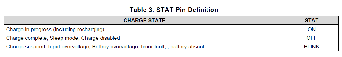
We have used the BQ24133 in previous designs and it has worked well. However, we are bringing up a new PCB design and are encountering some unknown issues. Here is our problem:
Application:
15V AC adapter -> BQ24133 -> 16V Boost regulator -> Smart Home Speaker (with large in-rush current during power up)
Battery pack: 12V, 3S1P
When the smart home speaker is connected to our circuit, the in-rush current is very large so the BATDRV pin automatically connects the battery to the input of the 16V boost (i.e. the speaker) to provide additional power. After the power up event, the additional current is no longer needed so the BQ24133 goes back into charging mode.
In our mass production design (that works) you can see the scope shot below that shows the BATDRV pin (blue) and the input to the 16V boost regulator (yellow) in the moment that the boost regulator is gated on through a power FET and the smart speaker starts to power on.
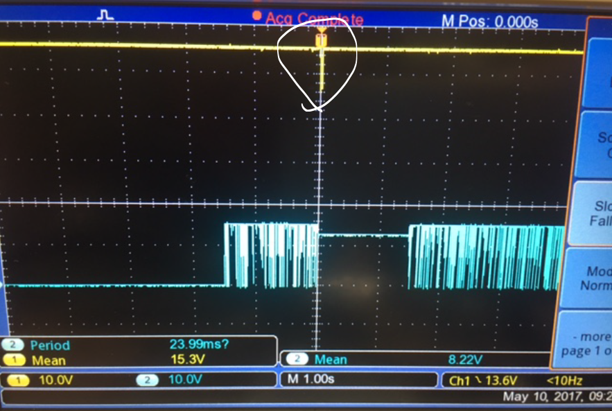
In this image, you can see the BATDRV pin (yellow) and the BQ24133 SW pin (blue) in a zoomed out time scale. When we gate on the 16V boost regulator and power up the speaker, you can see that the charger stops switching and then restarts. We seen the BQ24133 STAT LED go off and then back on, seemingly in sync with the SW pin. We don't know why the STAT pin is going off or why the charger starts to switch again. However, the application works fine this way.
In our new PCB design, that is a very similar schematic, we see the BATDRV pin engage, the SW pin stop, but then the SW pin never restarts. The STAT LED just continues to blink until we power cycle the input. This a show stopper in our application. When the speaker is turned on, we need the BQ24133 to continue charging, not get stuck in a fault mode.
This image is the same setup as the one above, but uses our new PCB design (yellow = BATDRV, blue = SW)
We are looking for some help with the following questions:
1) Do you have any idea why the BQ24133 is entering into the fault mode and not exiting?
2) Why in the first design does the STAT pin blink once but then the SW restarts?
3) Do you have another other ideas of what could be causing this?
Please see both schematics attached.Updated Design with BQ24133.pdf