This thread has been locked.

If you have a related question, please click the "Ask a related question" button in the top right corner. The newly created question will be automatically linked to this question.

LM5104: Part runs very hot, occasional failures.

Part Number: LM5104

Hello,

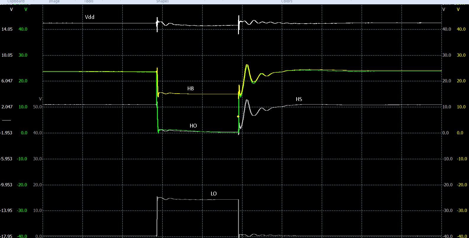
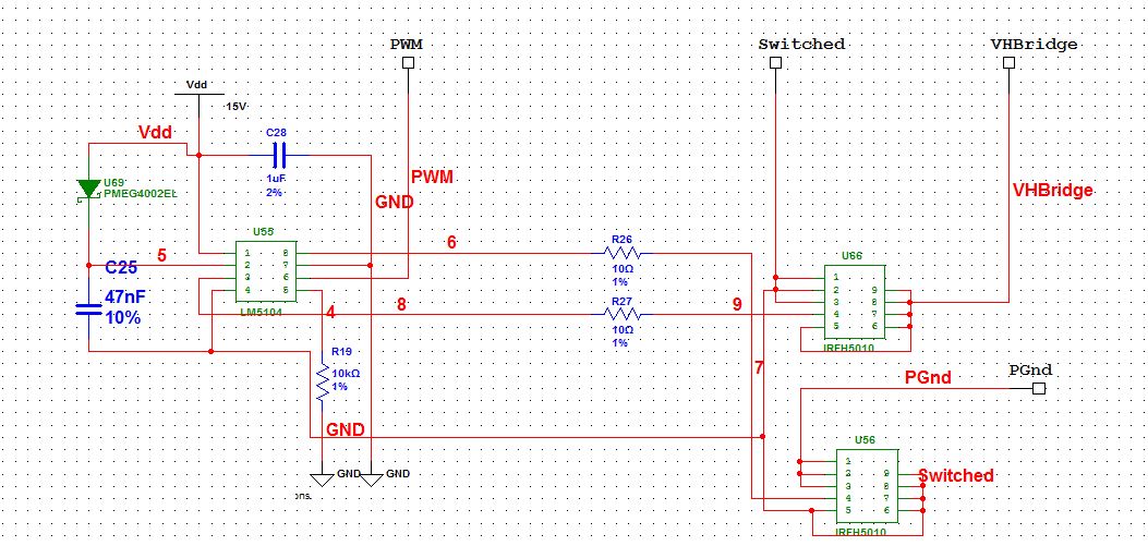
with the attached circuit I measure the temperature at the top of the LM5104 at around 70 celsius during normal operation. The device fails intermittently which may or may not be related to the temp. Package is the SOIC-8. LM5104 is being driven at 1kHz, 5%-95% duty. FETs are supplied with around 14.5v. Vdd is a 15v stabilised supply.

Thanks

  • P C39,

    Thank you for your interest in TI's LM5104 driver. I am one of the applications engineers for this device and will work with you to debug the behavior you are observing. At first glance, a running temperature of 70ºC does appear high for the conditions you describe, particularly the low switching frequency of 1 kHz. However, 70ºC is well within the operating conditions of the device and may not be related to the failure, as you observed.

    Thanks for including schematic and waveforms. Your schematic looks good. I would recommend a second capacitor at VDD, close to the device pins, in the range of 100nF to provide high frequency current during turn-on/off. From the waveforms it seems that VHBRIDGE is at 10V. Please confirm if this is the condition when the LM5104 fails. Also, what is the time scale for the waveforms shown? I am trying to determine the severity of the ringing on the HS pin.

    What happens when the device fails? Is it a temporary lack of functionality, or does the device appear damaged/non-functional? If possible, please check if there are shorts or restive paths between any of the HO/LO, HB/VDD, HS/PGND pins.

    In order to diagnose, let us try a few things to help pinpoint where the issue is coming from:

    1. To determine if related to the capacitive load conditions (PCB traces + MOSFET Ciss), please try running with R26/R27 removed from the circuit and check the temperature and for any incidence of the failure mechanism.

    2. To see if there is a need for more dead time, please try increasing R19 to 100kohm, running again, and checking as above.

    3. Try also adding turn-off diodes in parallel with the gate resistors as shown in the typical application section of the datasheet. This will result in faster turn-offs, which in turn should reduce power losses.

    PCB layout also can have an effect on performance. I can review the board layout for you if you share it.

    Regards,

    - Daniel

  • Many thanks for your prompt feedback Daniel,


    I have some results based on your recommendations:


    -          Replacing R26, R27 with 0 ohm links results in a significant temperature reduction.

    -          Replacing R19 with 100k has no measurable effect.


    To reply to some of your questions:

    -          VHBridge would normally be in the range 13.5-14.5v.

    -          The timebase in the attached oscilloscope waveforms is around 10us/division.

    -          The failures mechanisms are difficult to diagnose as there is often a lot of heat damage around the LM5104 and MOSFET area so it is difficult to determine whether the root cause is a failure of the MOSFETs or LM5104 since it is not usually possible to replace or test any of the components. It does appear that the failure results in both high and low MOSFETs conducting continuously. I have been assuming the LM5104 is the root cause because I believe the MOSFETs are operating well within their limits (100v Vdrain-source, 100A Id, 150 deg TMax etc) but I am beginning to wonder whether the results above suggest the MOSFETs are suffering shoot-through and subsequent damage. I have another failed unit which appears to have been removed before significant damage occurred so I will investigate this to see if it offers any insight.


    I would like to add the turn-off diodes you recommend but this would be difficult with parts that are currently in circulation whereas replacing the gate resistors with zero ohm links would be fairly straightforward. Would you recommend this since it seems to produce a reasonable reduction in FET/LM5104 temepratures?


    I will investigate the recently failed unit and try to answer your other questions.

    I have attached a screen shot of the PCB layout. Hopefully it makes sense to you!

    Thanks again,

    Phil


  • Phil,

    Thanks for the updates. The lower series gate resistances help drive the MOSFET gates on and off quicker, which in turn result in lower losses. Hence, the lower running temperature makes sense. I would recommend that you look at the slew rates on the SWITCH node to ensure you don't see undesired ringing. You may want to add a small resistance larger than 0hm (maybe 2 or 3ohm) to slow down the gates if you see fit. However, if the 0ohm links work out for you, then you can move forward like this and see if the catastrophic failures no longer occur.

    Regards,

    - Daniel