This thread has been locked.

If you have a related question, please click the "Ask a related question" button in the top right corner. The newly created question will be automatically linked to this question.

BQ24295: Charge / power supply

Part Number: BQ24295
Other Parts Discussed in Thread: TPS61088

We have used the bq24295 to both charge a single 18650 plus provide power for our product using the PMID pin.  Could you please review the Schematic below

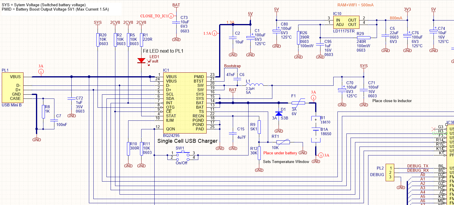
I have a couple of questions im not 100% sure about...

1. Looking at the functional diagram of the bq24295 (datasheet page 14) will we get conductivity from VBUS to PMID through the body diode of Q1 even if BATFET is disabled or is there an ideal diode on that path too?

2. Following on Does QON enable PMID from VBUS or just BAT (boost) to PMID?

Thanks

Rick

  • Hey Rick,

    Just a few of things I noted on your schematic:

    1) You may have a little too much capacitance on the PMID pin (judging by the 220uF I see just from this snippet. Please note the PMID acts as both the input capacitor to the buck conversion as well as the output capacitor for the boost conversion. I believe having too much output capacitance may affect the internal loop compensation we have for the power stage.

    2) You may have considered this offscreen (downstream), but just in case you didn't, make sure you have pull-ups for SDA and SCL lines.

    3) If you are trying to pull 3A from your input, please note you will need to decrease the LIM (R10) resistance to a lower value, according to the equation IIN = K_ILIM / R_ILIM in the EC table of the datasheet. Based on the resistance you have now, the charger will limit the input current to ~1.5A, and you will not charge at full desired charge current. The D+/D- detection will also provide an input current limit, but the charger will always select the lower of the two input current limits (Register based on host input/D+D- detection OR ILIM pin setting).

    4) A pull-down resistor (R11) is not needed for QON. It has an internal 1 MOhm pull-down.


    In regards to your questions:
    1) Even if the BATFET is disabled, the Q1. Conduction happens through the body diode initially and when the part is in HiZ mode, which can be set via the registers.

    2) QON is used for shipping mode. In this scenario, if there is no input power on VBUS and you have also disabled the BATFET, QON can be used to re-enable the BATFET and exit shipping mode. Any VBUS power will re-enable the BATFET. In your system, QON will re-enable the boost mode.


    Hope this helps!

    Regards,
    Joel H
  • Hi Joel H,

    Thank you very much for your comprehensive reply.  Good advice.  

    We do have pull up's up stream, and you are right in that we have too much capacitance.  We always design to remove components if not required so we will depopulate depending on pre-production test results.

    One question remaining is the current through Q1 while EN is LOW.  Is this the case?  Ie do we need to fit another MOSFET between PMID and our system 5V to ensure we can turn our product off and not drain the battery.

    Cheers

    Rick

  • Hey Rick,

    Could you clarify which EN = LOW you are referring to? Are you talking about the /CE pin? We do not have an EN pin on our charger.


    Regards,
    Joel H
  • Hi Joel,

    Apologies I am working on concurrent projects the EN pin was on a TPS61088. (I do not need any assistance with that).

    The question is .. In shipping mode will the body diode of Q1 conduct from VBUS to PMID?

    Cheers
    Rick
  • Hey Rick,

    In shipping mode, there is some leakage from VBUS to PMID. It is spec'ed in the EC to be around 3mA max. 

    To get into shipping mode, you must enable Hi-Z mode on the input to disable the converter and REGN and then disable the Q4 FET. If you plug in an adapter/power source, the converter will start again and you will exit shipping mode. 

    What is your concern with Q1 conduction from VBUS to PMID?

    Regards,

    Joel H