This thread has been locked.

If you have a related question, please click the "Ask a related question" button in the top right corner. The newly created question will be automatically linked to this question.

TPS2113A: Parallel diodes configuration

Part Number: TPS2113A
Other Parts Discussed in Thread: TPS2113

Hi,

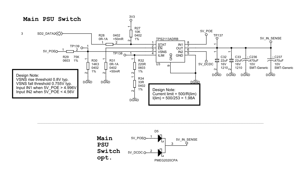
 my customer is using the attached circuit where he put 2 diodes in parallel to the device , just to increase current capabilities during peaks.

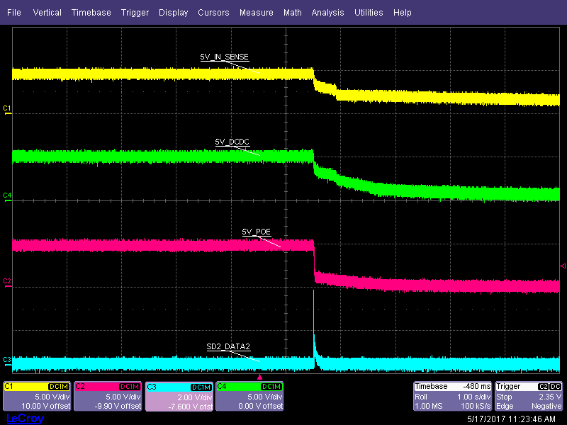
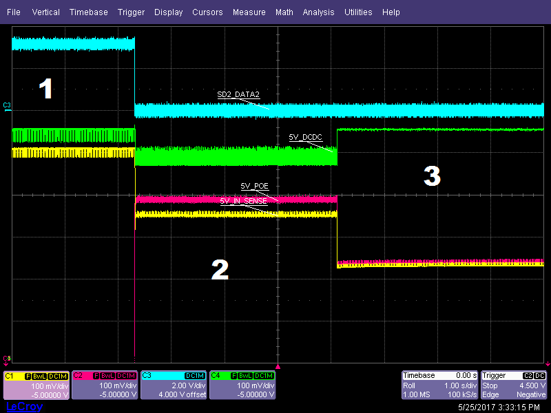
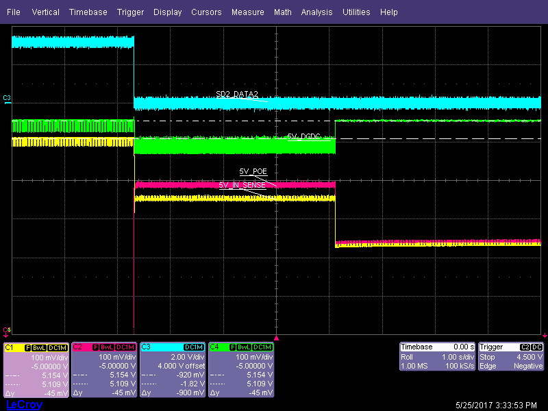
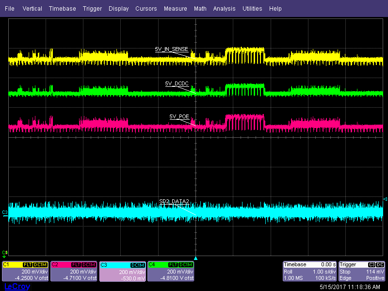
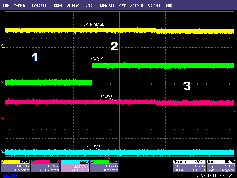
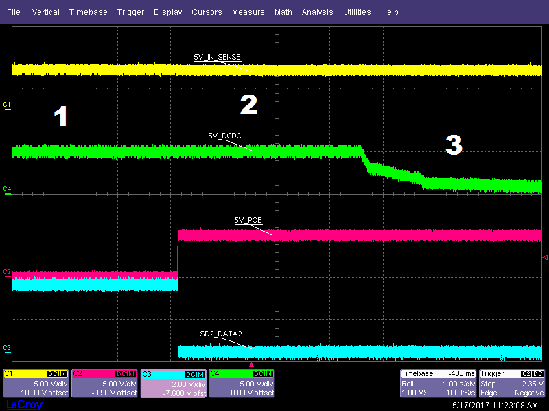
They noticed that with the diodes the circuit is not working(2nd picture) and POE(that is the output of Power over Ethernet stage) is stuck at 5V , even if it is supposed to go to 0V , and then output should switch to DC/DC ; in addition there is some noise on both input(DC/DC is an output of switching converter) and output.Without diodes(third picture) everything is fine.

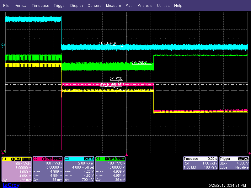
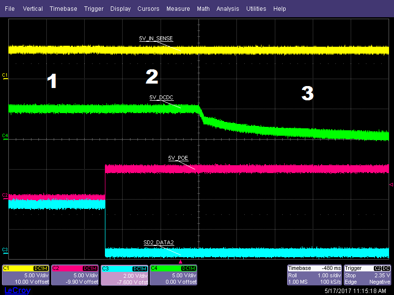
They did additional test with only one diode on POE or on DC/DC, just to understand the influence and with diode only on POE is OK, while on DC/DC NOK, see other waveforms.

POE will be stuck at 5V also if they disconnect POE cable.

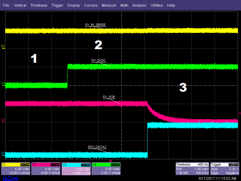
Can you verify what's happening?
Thanks

Umberto

  • Hi Umberto,

    Could you please point out which scope shot shows the issue and exactly what is being done to the device in this case (PoE is disconnected, DCDC is applied, etc)? I see a lot of scope shots where PoE is being brought low, and in your post it says that it is stuck at 5V. The output looks stable during all of the different transition cases.

    Thanks,

    Alek Kaknevicius

  • Hi Alek,

     sorry for the missing information; the filename has the explanation, but you do not see it in the attachments.

    Here it is from top to bottom:

    1- circuit schematic

    2-best example where you see that POE is stuck, both diodes used, noise in the output

    3- no diodes, everything works fine

    4-U3_signal_ONE_DIODE_ON_POE_switch_POE_to_DC

    5-U3_signal_ONE_DIODE_ON_POE_switch_DC_to_POE

    6-U3_signal_ONE_DIODE_ON_DCDC_switch_POE_to_DC

    7-U3_signal_ONE_DIODE_ON_DCDC_switch_DC_to_POE

    8-U3_signal_ONE_DIODE_ON_DCDC_all_off_zoom

    9U3_signal_ONE_DIODE_ON_DCDC_all_off

    In conclusion, with a diode only on POE, the device works fine

    With only the diode on DC/DC, there is the problem and POE get stuck at 5V even if POE cable is disconnected.

    in all_off you see that disconnecting 5V DC, STAT pin does strange on/off switchings.

    Pls let me know if you have any explanation of this behavior.

    Thanks

    Umberto

  • Hi Umberto,

    Thanks for the detailed explanation here, I believe I know what is going on.

    The TPS2113A only switches from IN1 to IN2 when IN1 is low. During normal operation, when PoE is disconnected, there is nothing keeping IN1 up, so it decays and IN2 takes over.

    When a diode is put from IN2 to OUT, IN2 is now able to power the output of the solution. When PoE is disconnected, IN1 is left floating, and the diode connection from IN2 to OUT keeps the output high. The FET from IN1 to OUT is still on, so IN1 follows OUT, meaning that it will be at the same voltage as the output: IN2 - a diode drop. 

    Because IN1 never drops, the device is never able to switch to IN2. The switch to IN2 is what turns off the FET from IN1 to OUT, blocking reverse current.

    Does this make sense?

    Thanks,

    Alek Kaknevicius

  • Hi Alek,

     I'm working on the circuit illustrated by Umberto.

    Thanks for your explanation, I've made some measurements on the circuit in order to verify it.

    Below the waveforms during the connection/disconnection of the POE power source:

    Phase 1: Only 5V_DCDC is present. From 5V_DCDC to 5V_IN_SENSE there is a 45mV voltage drop (by TPS2113)

    Phase 2: Both 5V sources are present. TPS2113 switch from 5V_DCDC to 5V_POE and the voltage drop is 35mV (by TPS2113)

    Phase 3: The POE source is turned off but the 5V_POE remains. From 5V_DCDC to 5V_IN_SENSE there is a difference of 320mV (diode forward drop) and 5V_POE has the same value of 5V_IN_SENSE.

    This confirms your supposition, the TPS2113 do not switch from the IN1 to IN2 and the P-MOS remains to the conduction state (OUT and IN1 have the same voltage level). The power comes from 5V_DCDC rail through the diode and it drives both 5V_IN_SENSE and 5V_POE.

    Voltage drop from 5V_DCDC to 5V_IN_SENSE during phase 1:

    Voltage drop from 5V_POE to 5V_IN_SENSE during phase 2:

    Voltage drop from 5V_DCDC to 5V_IN_SENSE during phase 3:

    The discussion can be marked as answered.

    Thank you for the technical support,

    Matteo Silotto

  • Hi Matteo,

    Thanks for your response here.

    Cheers,

    Alek Kaknevicius