This thread has been locked.

If you have a related question, please click the "Ask a related question" button in the top right corner. The newly created question will be automatically linked to this question.

LM25011: DCDC Converter does two cycles in quick succession and then pauses.

Part Number: LM25011

I implemented a DCDC converter: 24V nominal to 5V at 2A.  Webbench suggested the LM25011. My circuit is now operational, and seems to function quite well, although it gets a bit hot....  I just measured: 25V @470mA, 11.75W, 5V at 2A out: 10W. So we should be seeing about 1.75W  of losses in the DCDC part. (and currently 0.12W in the trace to the output connector... already fixed in the design). 

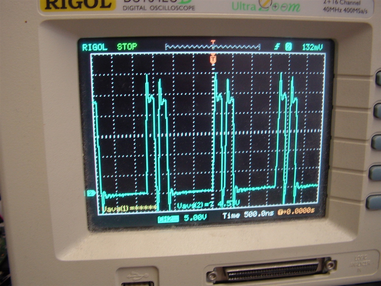
Anyway, the output looks fine, but the scope on the switching node shows something I didn't expect: There are two pulses close together and then a bigger gap before the next. Looks as if it is cycle skipping or something like that. But at 2A I shouldn't be "near idle", right?

So... Is this normal / expected behaviour, or should I change something?

P.S. bugreport:  On the main ti.com website, when I click support, I can chose product support, but then when I click "

The same "nothing happens" when I browse to "report an issue with the website"..... 

  • Hi Roger,

    Thank you for your question.

    The LM25011 has a Constant On Time architecture which requires sufficient amount of ripple (>50mV) on the FB pin to ensure that the behaviour you see does not occur.

    Please refer to Section 8.2.2 on page 20 of the datasheet to prevent this "double pulsing" behaviour. We recommend using the Option B ripple configuration circuit to ensure proper functionality.

    Best regards,
    Gautam Hari
  • Going through all the calculations in the datasheet is a bunch of work. So I used "webbench". Even when today I insert my parameters I get the same design as what I implemented. Oh, wait. Webbench suggests a 9 mOhm output capacitor. I interpreted that as 9mOhm or better. Maybe I even added an extra 100nF to lower the effective ESR even further... OOops. Counter productive.

    So... I'll remove the 100nF if indeed it is there, and see if the double (and sometimes tripple pulsing keeps happening.
    Would using a longer (narrow) trace between the inductor and the output capacitor work? And have the FB resistors connect close to the inductor?

    According to the thermal simulation, if I interpret that correctly, it's the chip that gets the hottest. In my implementation, my feeling (I don't have an IR camera) is that the inductor gets the hottest. My notes mention the exact webbench-suggested inductor as "cheapest solultion, should work", and I have now selected a "slightly beter" one that is rated for 4A instead of 3.6 and has 15 mOhm ESR as opposed to 24moHm. This could be caused by the double pulsing, right?

    Suppose I buy this capacitor nl.farnell.com/.../2525130 , I can't find any ESR spec in the datasheet. The only mention of ESR is in hte feature list: "low ESR".