This thread has been locked.

If you have a related question, please click the "Ask a related question" button in the top right corner. The newly created question will be automatically linked to this question.

TPS65217: Failures with DDR on the board

Part Number: TPS65217

Hi Team,

Can you please assist my customer with their inquiry below?

Thanks for the help!

________

we are seeing some failures with the DDR on the board. In one of these boards, we detected the DDR voltage to be 2.9V yesterday. It is not always that high, but it seems to happen randomly on some units. Here are the details.

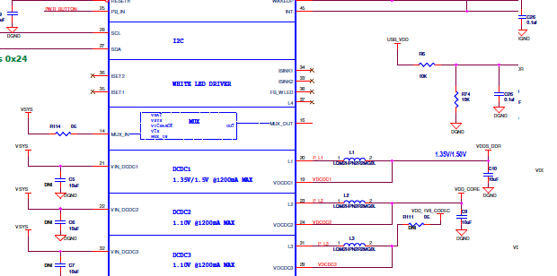
1. PMIC used - TPS65217D
2. DDR used - Hynix H5TC4G63CFR
3. The PMIC has a default output voltage of 1.35V on DC-DC1. This is routed to the DDR. The rail is not modified by SW.

Can you think of any reason why the PMIC can source voltage as high as 2.9V? We have only one known observation, but we have seen several DDR failures.

  • Hi OD,

    I will assign your query to TPS65217 expert and we will get back to you.

    Regards, Juha
  • Can you share a schematic of the TPS65217D in the application? If the whole PDF cannot be shared, a screen shot of the DC-DC1 output pins would be helpful.

    If the schematic is unavailable, we will need to know the following at a minimum:
    -Value of inductor
    -Total capacitance at SYS pin
    -Total capacitance at VDCDC1
    -Any resistors connected between L1 and VDCDC1


    Some additional questions about the issue you observe:
    -When the voltage goes up to 2.9V, how long does it stay there?
    -Does the spike up to 2.9V happen at start-up or randomly during operation of the circuit?
    -Do other rails also go up to values higher than expected, or just DC-DC1?
    -Is there a battery in the system?
  • Hello Brian,

    Following is the snap shot:

    If the schematic is unavailable, we will need to know the following at a minimum:
    -Value of inductor - 2.2uH
    -Total capacitance at SYS pin - 39.4uF (10uF x 4 + 4.7 x2)
    -Total capacitance at VDCDC1- 52.1uF (10uF x 5 + 21x 0.1uF)
    -Any resistors connected between L1 and VDCDC1 - NO


    Some additional questions about the issue you observe:
    -When the voltage goes up to 2.9V, how long does it stay there? - It was there until we reboot the system. Unfortunately, when we rebooted, it became 1.35V again and we could not reproduce it
    -Does the spike up to 2.9V happen at start-up or randomly during operation of the circuit? - Only once we could see this. We were not able to reproduce this.
    -Do other rails also go up to values higher than expected, or just DC-DC1? We measured DCDC2 which was normal (1.1V) and DCDC3 (1.8V - we are writing to the PMIC register to make this one 1.8 after booting)
    -Is there a battery in the system? YES. Li-Ion

  • Paul,

    I've never seen this issue myself, and there doesn't appear to be anything wrong with your schematic or component selection.

    My recommendation would be to try to reproduce it and determine the stimulus which causes the voltage to spike up. I suggest that you try to think of corner cases which happen infrequently and then re-create these conditions using a combination of power supplies and arbitrary waveform generators.
    If you can determine the cause, then I would recommend you try to reproduce it on multiple PCBs.

    Unfortunately, if you experienced the problem and cannot reproduce, it would be quite difficult for me to reproduce it.
  • Thank you for the response Brian.

    I tried to re-create this condition in many ways, I could think of:

    (1) Heating the component up to 65 degree Celcius and powering on

    (2) Powering on the board and while it is running, heating the board with a hot air blower

    (3) Trying to short one of the dataline of DDR to 3.3V (a destructive test) and see if the DDR power plane is shifting - assuming some soldering issue on the board

    But in all the cases, the board was working and the voltage at DCDC1 remained 1.35 to 1.36V

     Another observation is that we are seeing this problem after we put the PCBA inside the product enclosure and do an ultrasonic welding. The ultrasonic welding frequency is 20KHz. Do you think this mechanical vibration can cause some thing fail in the PMICs power section?

    Thanks and regards,

    Paul

  • Paul,

    I'm not an expert of EMC, but I do know that 20kHz is on the high-end of the audio band and high frequency audible noise is direction-dependent. If you can hear the ultrasonic wielding, then there is a lot of energy and pressure being forced onto the PCB that is bouncing back into the room.

    A mechanical failure would probably be visible and the damaged PCB would continue to be damaged after the wielding is complete. 

    Have you tested PCBs after the damage is observed? Is it reproduce-able on these PCBs but not on "new" PCBs out of the enclosure?

    To determine if 20kHz is a resonant frequency of an RLC combination, you could do some math on the components selected.

    You could also try to do some "low-frequency" conducted emissions testing at 20kHz to see if that energy is being converted into electricity on the VDCDC1 node. If you have the right equipment, the test can be done on a "new" PCB outside the enclosure.

  • Brian,

    While we do ultrasonic welding, the Unit is powered off.

    If there was a mechanical damage, it would continue to be damaged after the welding process as you have mentioned. But the mystery is that once we replace the damaged DDR with a new one, it continues to work without any issue. So the probability of some PCBA damage or component damage is less - this is what I think.

    And one observation is that (we do not have much sample data) most of the time it is failing in the first charge cycle after US welding.

    Thanks and regards,

    Paul

  • Brian,

    I would like to re-open this issue to see if you could give some inputs. We were able to get more boards with this failure during production test. And following are a few more inputs. Could you please let me know if any hint you can provide.

    (1) When the DCDC gets this problem out voltage is in the range of 2.9 to 3.1V
    (2) During this time, we could get all the PMIC registers dump and every thing looked ok. Software did not modify the PMIC registers
    (3) We tried writing to the PMIC registers to lower down the voltage. I2C write happened. But the output did not change and it was stuck at 3.0V
    (4) I probed the inductor pin near to the PMIC which is supposes to pulse. But it was stuck at 3.0V and was not toggling

    This indicates that the DCDC has gone out of control. However all other DCDCs & LDOs were working fine.

    Could you please let me know what are the conditions in which PMIC can go to unstable state like this?
    Will more capacitance on the output will affect the control loop's stability?

    Difficult part is that the same board will work fine after reboot and we will not be able to reproduce this.

    Our production is affected by this issue and we request your support on this

    Regards,
    Paul
  • Hi Paul,

    I'm reaching out to the team to review your inquiry. Apologies for the delay.

    Respectfully,
    Omid
  • Paul,

    Were you able to record any scope shots of the issue occurring?
    Please capture at least the following signals: DCDC1, SYS, PWR_EN, and VIN (AC/USB/BAT). A point of interest would be where DCDC1 crosses over 1.35V on its way up to 3V: does it level off for any amount of time?
    If you have a logic analyzer (e.g. Saleae), it would be helpful to also capture I2C during the scope captures and trigger on same edge.

    Since the issue does not occur at all times, it would also be beneficial to see the normal power-on sequence without the issue (VDCDC1 = 1.35V), recording the same channels on the scope.

    Maybe you can remove the DDR IC on a board that has the issue or just keep testing an already damaged PCB, but it will be quite difficult to debug the issue with no visuals to study.

    Thanks,
    Brian