This thread has been locked.

If you have a related question, please click the "Ask a related question" button in the top right corner. The newly created question will be automatically linked to this question.

tps709: TPS70950DBVR

Part Number: TPS709
Other Parts Discussed in Thread: TPS709

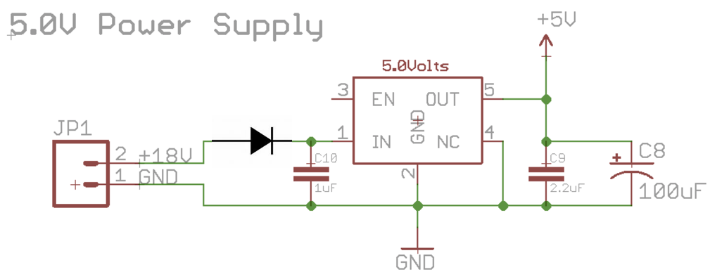
Hi, I'm testing the TPS70950DBVR. Here is the data sheet:

http://www.ti.com/lit/ds/symlink/tps709.pdf

It says it can run from inputs up to 30VDC, but I'm having trouble.  I setup a set PCB with the 2 Caps, like in the data sheet, and powered it from a 12VDC bench top power supply (actual reading is 13.8VDC).  Using LEDS, I added a load to the output to create about 40mA of draw.  It all worked fine.  I checked the temperature of the chip using a K-type thermocouple, and it only raised about 5 degree, to 40 degrees celsius.

   So then I removed some of the load, so it was only drawing about 18mA, and changed my input voltage to a 18VDC lithium battery pack (actual reading is 20.1VDC) The regulator immediately burnt up.  I've done this twice.

My soldering all seems good. I was very careful the second time round to get a good solder reflow.

Can you tell me what the problem is?

Here's a photo of the PCB copper


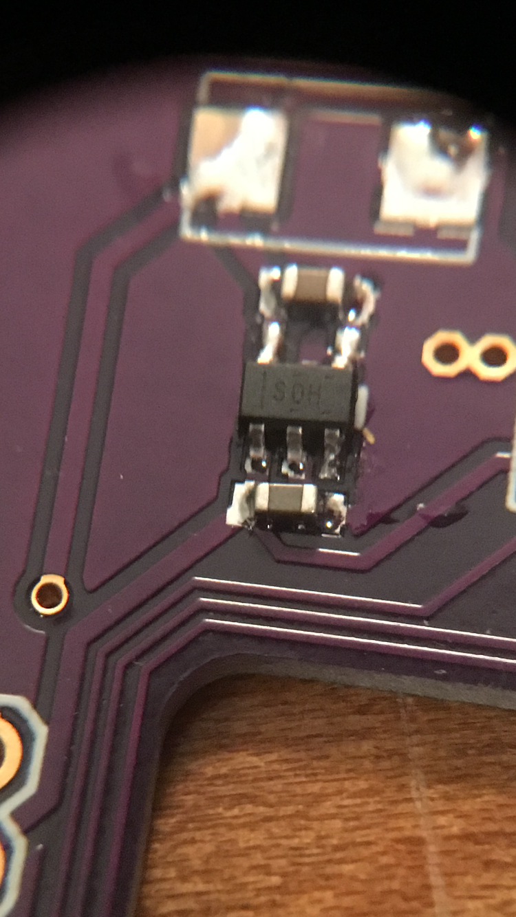
...and a photo of the chip and caps in place.

Like I said, the load was rather light-just 2 LEDS drawing 18mA total when powered with the 13.8 volts, so there wasn't a lot of load on the regulator.  Is it not made for 20 VDC?

  • HI Charlie,

    The TPS709 can definitely support the input voltage range for your application. its absolute maximum is 32VDC. Some how in you application something is getting violated. Any transients beyond the absolute maximum ratings can damage the device.

    Are you using an electronic load and is active when you remove the bench supply and attach the battery? Does your test set-up have long leads (which could be inductive and creating positive or negative transients which could damage the device). Could you capture oscilloscope shots of VIN and VOUT when removing the 12V bench supply and then adding the battery pack?

    Regards,

  • Attached is the email I responded, but it was rejected.Re_ Linear Regulators Forum_ tps709_ TPS70950DBVR.rtfd.zip

  • Hi Charlie,

    From what you have shared, I can not seen anything obvious. Seeing a scope shot of Vin and Vout when the battery is connected could help.

    Is there any chance that the battery is being connected with reverse polarity? The TPS709 can protect against current flowing from Vout to Vin, but it does not have reverse polarity protection. This could be accomplished by putting a diode in series with Vin.

    Without seeing more, I can only guess that this is the issue.

    I hope this helps.