


Other Parts Discussed in Thread: LM27403, TPS40304A, TPS546C23, TPS546C20A
I had the same question on May 19, 2017.
But I have not received any reply to this day.
So I ask for help again with almost the same content today, with the same content.
I would like to find a DC-DC with a variable output voltage by receiving a feedback (or an external pin).
I am requesting a DC-DC recommendation.
-----------------------------------------------------------------------------------------------------------------------------
[The question on May 19, 2017]
A. Circuit Design Purpose
(1) I am designing a constant current source module to be satisfied the following specifications.
- Vin = DC 12V.
- Vout = (0.0 Vdc) to 1.8 Vdc
- Iout = DC35A
(2) The current is higher than the output voltage, so I must have use VID(LM10011).
However, Vout of DC / DC should be changed
from minimum 0.XVdc (about 0.6Vdc) to maximum 1.8Vdc
according to input state of FB, and current should be supplied up to 35A.
B. Operation.
We will design based on the figure below (LM10011 datasheet).
However, unlike the picture,
Vdd=5Vdc(fixed) of the LM10011 and Vin=12Vdc(fixed) of the DC/DC.
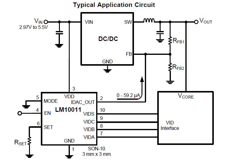
(1) The MCU should control the input(VIDS,VIDC,VIDB,VIDA) of LM10011(6bit)
so that the DC/DC Vout is soft start(0.6V -> 1.8Vdc) and soft stop(1.8V -> 0.6Vdc)
(2) The IDCA_OUT output of the LM10011 is input to the "FB" of the DC/DC as shown in the figure.
(3) We will measure the output(Vout) current of DC/DC with sensor.
(4) The MCU receives the measured current value and monitors normal operation or overcurrent status.
(5) During the time that the LM10011 is on(about 30 minutes),
Adjust the IDCA_OUT output of the LM10011 to maintain a constant current (approx. DC 35A).
(6) During the "On time(about 30 minutes)" of the LM10011 ,
the MCU must control the IDCA_OUT output of the LM10011 to maintain constant current (approx. DC 35A).
C. Inquiries
I went to TI.com to look for "DC/DC" to match the above behavior.
For use as a constant current source, I looked for a DC/DC variable Vout according to the DC/DC FB.
In addition, the DC/DC had to satisfy both input and output specifications.
So I want to use "TPS546C23".
However, the "PMbus" of the TPS546C23 is too difficult for me.
(1) If I don't use the "PMbus" of the TPS546C23, can I use the TPS546C23 as the above DC/DC?
(2) If not, even if it bother you, please recommend a suitable model for me.
Thank you for reading this.


