This thread has been locked.

If you have a related question, please click the "Ask a related question" button in the top right corner. The newly created question will be automatically linked to this question.

TPS2492: TPS2492

Part Number: TPS2492

Hey,

We are using the TPS2492 in a new design as a High Side Load Cut Off switch in a 24V electronic.The supply input voltage is 24V and one requirement is that the TPS2492 should switch off the output in case off overload or short. Now we have finished our first prototype boards and have checked the function. One test case was to apply a direct hard short on the 24V output directly after the output capacitor during normal operation any time when the TPS2492 is in on state. When we do this we measure the following figure:

Yellow= output voltage, Blue: 3.3V logic supply voltage in the system, green = output current

We see, that the TPS2492 switch of the short, but a verry high current impulse (ca. 130A) happens with a verry high slew rate. This generates an crosstalk to other supply voltages in the system (like 3.3V or 5V supply).

So my question was: Do you have experience with the handling of hard output shorts during normal operation? I have doubts because of this sharp & high current impulse because of influence and crosstalk problmens into other lines in the circuit. How does other customers handle this case. I'm thinking about to add an additional output serial inductance for limiting the current slew rate and for give the TPS2492 time for cut off and eliminate the high current peak? Do you have some tipps or proposals?

  • Hi Hubert,

    Welcome to E2E!  I don't believe the waveform pic came through. Could you please try to reattach? Click on the "Use rich formatting" on the bottom and make sure the file name is not long (try calling it temp1). Also, if possible please attach a picture of the schematic showing our part and everything connected to it.

    The TPS2492 can handle hard output shorts if designed within the SOA of the FET. The best way to figure out if a particular design will work with one of our hotswap controllers is to fill out our design calculator tool with this device and attach. This will help review and troubleshoot your design, and would greatly speed up the back-forth communication of questions we would have for information needed for the review (such as total output cap including anything connected downstream from the output node, which may not be shown on a partial schematic). 

    You can find it by going to www.ti.com/hotswap ==> click on “Tools & software” ==> then click on “Hot Swap design calculator tools”

    For help on filling out the excel spreadsheet, we have video tutorials. They explain how to enter the correct values cell by cell. Please watch the videos at www.ti.com/hotswap ==> Click on “Support & Training” tab. 

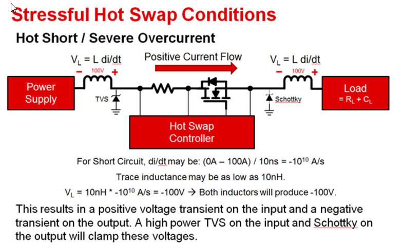
    On another note, we recommend all designs with hot swap controller to have a TVS diode on the input and a Schottky diode at the output for transients. All wires have trace inductance and in the event of a hot short or severe overcurrent, those wires could produce a huge change in voltage at the input and output. I recommend the B380-13-F Schottky diode and the 5.0SMDJ for the TVS diode. 

    Best Regards,

    Aramis P. Alvarez