Hi,
I have a design that uses a couple of TPS63000 devices to create a 3.3V and 5V power supply from a Lithium-Ion battery (and a TI charger/power management IC). I initially experimented with the evaluation board and built several prototypes with great success.
Our first batch of production product arrived the other day but I instantly noticed a problem. After a bit of investigation the 5V power supply output was oscillating - I had approx 2V peak to peak signal sitting around 4.5V at about 96kHz. Three boards were tested at random from the production batch with the same issue.
While the power supply was oscillating the input current was significant (even with no output load) at around 200mA and the device got warm to the touch.
The normal circuit load on the output of this power supply is about 100mA. I tried disconnecting the load, but the oscillation was still present, just slightly less ripple.
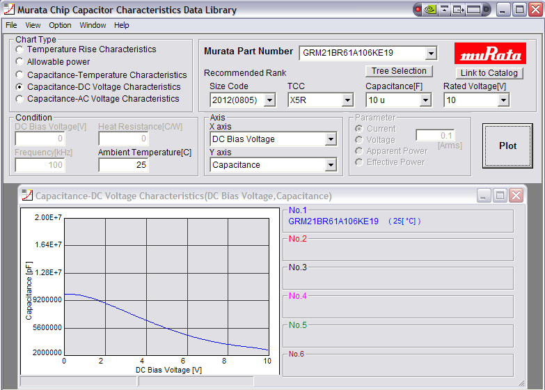
The layout follows the development board (I can upload if necessary) and uses a 10uF 0805 ceramic on the input (10V, X5R), a 3.3uF inductor, an identical 10uF 0805 ceramic capacitor on the output with 100n 0603 in parallel.
I slowly migrated a component at a time over to the development board starting with the feedback network, then the inductor, then the output capacitors then suddenly the oscillation occurred on the output of the dev board (with no load or 100mA load present, at 3-4V input).
The 0805 10uF 10V ceramic output capacitor (I can get the exact part details when I am back in the office tomorrow) appears to be causing the problem. What is interesting is that there is no oscillation at 2V and 5V input, and as you ramp the input voltage over this range the oscillation builds up then diminishes.
I have a solution, I tried two 10uF 0603 6.3V capacitors on the output (as per the dev board) and have not seen the oscillation since, over the full input range and with no load or 400mA load, and with load transients.
However, I would like to know what could have caused this issue so I can avoid this in future? I used a 10uF ceramic and regardless of load I got nasty oscillation on the ouput - even on the development board supplied by TI?!
For the record, I also tried adding the feedforward cap in parallel with R1 on the feeback network but this had very little effect.
Just on the point of the output capacitor selection, could someone explain the equation in the datasheet - what values do I use for uF/uH?
Thanks in advance,
Mark