This thread has been locked.

If you have a related question, please click the "Ask a related question" button in the top right corner. The newly created question will be automatically linked to this question.

BQ24133: BQ24133

Part Number: BQ24133

Hi Dear,

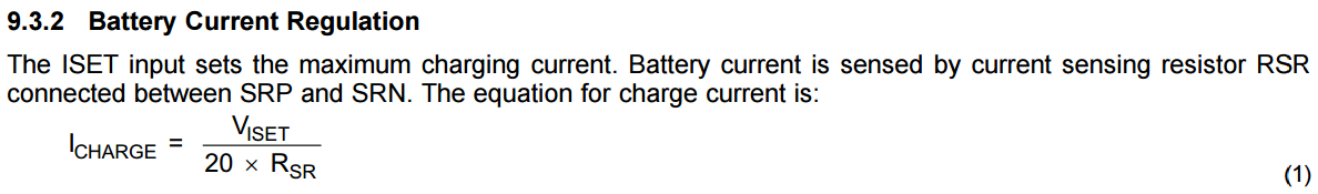
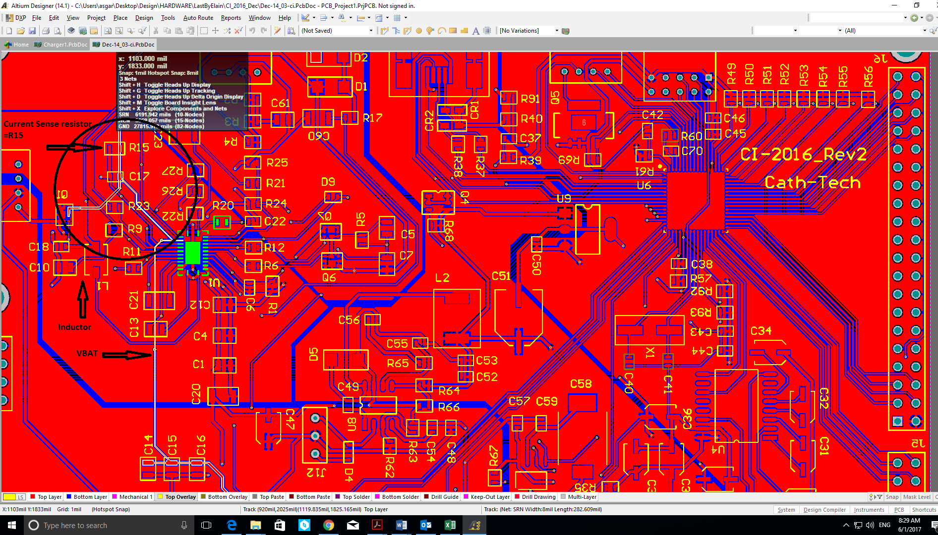
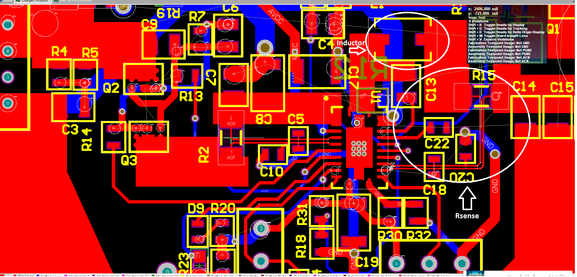
I am using bq24133 Ic charger, my charger current does not exceed from 240mA since I used Rsense 0.01 ohm, I need PCB layout since I think that my the problem is because of my PCB layout.

Thanks in advance

Elaine

  • Hi Elaine,

    For the layout, you can refer to datasheet section 12.1 Layout Guideline bq24133 and EVM guide bq24133EVM section 4.2 Board Layout.

    What is your ISET setting? Did you check the VISET? Did it follow the charging current setting shown below?

    Best regards,

    Ann Lien

  • Thanks for your response Ann,

    My Iset capacitor are 32.4K and 232K which is supposed to give me about 2mA.

    and the Iset voltage is 0.4.

    I think something wrong is with the PCB layout, specially for current sense resistor which is not according to layout guideline in the datasheet. moreover routing analog ground is not separately from power ground...

    I attached the PCB (In fact the former designer has drawn that) ,


    Also I attached the new one that I am drawing and I just want to make sure that it is ok .

    I was looking for a PCB layout file like bq24133EVM PCB file if it is possible.

    I also should mention that our PCB  has in 2 layer.

    thanks in advance.

  • Hi Elaine,

    Your ISET is 0.4V so the charging current limit is 2A.

    According to the first layout, It can't be that because the sensing trace couldn't connect to other component besides filter cap. I think your new layout is good for the RSR sensing. One more little thing, you can modify the trace at the corner to let this two trace has equal length.

    May I confirm the issue occurred in the original design or the new design?

    For the layout file, you can refer to EVM user guide. It is clear for the 4 layers layout design.

    Best regards,
    Ann Lien
  • Thanks Ann,
    Issue occurred in the original design, I haven't tested the new one, I just want to order it.
    saying" It can't be that because the sensing trace couldn't connect to other component besides filter cap." you mean that charge current can't be 2A or you mean that it can't be the cause of problem? would you please clear that for me?
    Cheers,
    Elaine
  • Hi Elaine,

    It means you can only connect sensing trace to filter cap, cannot connect to other components like inductor or BATFET.
    It may be the cause for the sensing error. So your new design is good for sensing trace, you can try it to confirm if the charging current follows your setting.

    Thanks,
    Ann Lien
  • Hi Ann,

    My new board received but there is no output with charger! it can switch when there is battery but it can not work with charger.  Actually Vref is 3.9 which is overload but I don't know what should be the reason, do you have any idea about that?

    Cheers

    Elaine

  • Hi Elaine,

    Is Vref=3.9V every time you power up? If yes, could you provide your schematic and help me to check if the IC is normal? Vref should not be 3.9V. If not, could you check the charging condition in datasheet if there is anything wrong?

    Thanks,

    Ann Lien

  • Hi Ann,

    Thanks for your help. There was a soldering problem , in fact Termal pad wasn't solder. I removed the IC and soldered again, issue was fixed.

    Thanks

    Elaine,

  • Hi Elaine,

    Thanks for your work in debugging! Please let me know if there is anything I can help!

    Thanks,
    Ann Lien