This thread has been locked.

If you have a related question, please click the "Ask a related question" button in the top right corner. The newly created question will be automatically linked to this question.

UCD3138A64: How to configure UART for UCD3138A64?

Part Number: UCD3138A64

Hi,

I'm trying to get UART working on UCD3138A64OEVM-662 eval board. I've got "partial success", please help me get to the "full success" - I bet the problem is something "stupid".

This is how I initialize UART:

#define UARTREGS    Uart1Regs
int uart_init(unsigned int baudrate)
{
    const Uint32 brval = (15625000 / 8 + baudrate / 2) / baudrate - 1;
    UARTREGS.UARTCTRL0.bit.SYNC_MODE = 1;          //asynchronous
    UARTREGS.UARTCTRL0.bit.DATA_SIZE = 8 - 1;      //8 bit payload
    UARTREGS.UARTLBAUD.bit.BAUD_DIV_L = (brval >> 0) & 0xff;
    UARTREGS.UARTMBAUD.bit.BAUD_DIV_M = (brval >> 8) & 0xff;
    UARTREGS.UARTHBAUD.bit.BAUD_DIV_H = (brval >> 16) & 0xff;
    MiscAnalogRegs.CLKGATECTRL.bit.SCI1_CLK_EN = 1;
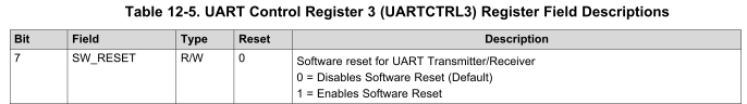
    UARTREGS.UARTCTRL3.bit.SW_RESET = 1;
    UARTREGS.UARTCTRL3.bit.SW_RESET = 0;
    UARTREGS.UARTRXST.bit.RX_ENA = 1;
    UARTREGS.UARTTXST.bit.TX_ENA = 1;
    UARTREGS.UARTTXST.bit.TX_WAKE = 1;
    UARTREGS.UARTIOCTRLRX.bit.IO_FUNC = 1;         //UART RX
    UARTREGS.UARTIOCTRLTX.bit.IO_FUNC = 1;         //UART TX
    return 0;       //so far ignored
}

sending data:

#define tx_rdy()    UARTREGS.UARTTXST.bit.TX_RDY
#define tx_send(b)  (UARTREGS.UARTTXBUF.all = (b))

int uart_try_send(int d)
{
    if( !tx_rdy() ) return 0;
    tx_send(d);
    return 1;
}

int uart_send(const char string[], const unsigned int len)
{
    unsigned int i;
    for( i = 0 ; i < len ; ++i ) { while( !uart_try_send(string[i]) ); }
    return len;
}

and in the main it goes:

const char hello_text[] = "It is me!\n";
    uart_init(9600);
    uart_send(hello_text, 10);

this is done before the main loop which calls pmbus_handler. The program does nothing more.

I build it using Code Composer 7 under Windows and use UCD3xxx GUI to program and debug.

The result is that TX line goes high (idle) after entering program mode, and becomes low again after entering ROM mode, what partly is the expected behaviour (thus "partial success").
But my oscilloscope shows no transmission from the IC.
The debugger in the UCD3xxx GUI says that the TX buffer contains the last sent character of hello_text, ie. '\n' (code 0x0a).
The TX_RDY flag is set to 1.
UART does not receive anything - RX_RDY remains 0 and RX buffer remains unchanged.

This looks like something was preventing the output from / input to UART - are there any other registers used to configure pins?

I've connected the oscilloscope to J25, pin 3. For reception on PC I've put on a jumper at pins 2 & 3.

For reception at UART I've put on a jumper on J23, pins 2 & 3.

For communication with a PC I'm using an USB-to-RS232 converter (but this only "confirms" the no-result shown by the oscilloscope).

The Fault3 line is pulled LOW (this is the "backdoor" from training labs).

Best regards,

Adam

  • Here's some simple UART code which works. I'd suggest starting with this, and then adding the baud rate calculation and other features later.

    I remember that you need to transmit the first byte to kind of prime the pump.

    This code is for 38400. I think that 9600 should be 202 in the lowest byte of the divider instead of 49

    I'm amazed and mystified by your baudrate calculation, especially that you can declare a constant that incorporates a parameter which is passed from the calling function. I've never seen a temporary constant before, I guess it makes sense?

    And maybe the purpose of the baudrate/2 is to round the result?

    I guess in about 44 years of programming, I've always been presented with a single fixed baud rate.

    void init_uart0(void)
    {
    volatile unsigned char rx_byte;

    Uart0Regs.UARTCTRL3.bit.SW_RESET = 0; //software reset while initializing UART

    Uart0Regs.UARTCTRL0.bit.DATA_SIZE = 7; //8 bits
    Uart0Regs.UARTCTRL0.bit.STOP = 1; //2 stop bits
    Uart0Regs.UARTCTRL0.bit.SYNC_MODE = 1; //asynchronous mode

    Uart0Regs.UARTHBAUD.bit.BAUD_DIV_H = 0;
    Uart0Regs.UARTMBAUD.bit.BAUD_DIV_M = 0;
    Uart0Regs.UARTLBAUD.bit.BAUD_DIV_L = 49; //for 38400 //47 for control board, 44 for open loop

    Uart0Regs.UARTRXST.bit.RX_ENA = 1 ;//enable RX

    Uart0Regs.UARTTXST.bit.TX_ENA = 1;//enable TX

    Uart0Regs.UARTINTST.all = 0xff; //these two statements are supposed to clear the status bits
    Uart0Regs.UARTINTST.all = 0;

    rx_byte = Uart1Regs.UARTRXBUF.bit.RXDAT; //clear RXRDY flag

    Uart0Regs.UARTIOCTRLTX.bit.IO_FUNC = 1; //enable transmit pin
    Uart0Regs.UARTIOCTRLRX.bit.IO_FUNC = 1; //enable receive pin

    Uart0Regs.UARTCTRL3.bit.CLOCK = 1; //internal clock select;
    Uart0Regs.UARTCTRL3.bit.SW_RESET = 1; //software reset released UART init done?

    Uart0Regs.UARTIOCTRLSCLK.bit.IO_FUNC = 0; //disable external clock for UART.

    Uart0Regs.UARTTXBUF.all = ' '; //put out a byte to get things started.
    }

    void char_out_0(char data)
    {
    volatile char rx_byte;

    while(Uart0Regs.UARTTXST.bit.TX_RDY == 0)
    {
    if(Uart0Regs.UARTRXST.bit.RX_RDY == 1)
    {
    rx_byte = Uart0Regs.UARTRXBUF.bit.RXDAT; //clear RXRDY flag
    }
    pmbus_handler();
    }
    Uart0Regs.UARTTXBUF.all = data; //put out a byte
    }
  • Thanks again, Ian!

    This code in fact makes UART transmit data.

    The thing that I would have never guessed is to assert SW_RESET for setting the configuration.
    I can't find anything about that in the Technical Reference Manual.
    And actually, it seems that this documentation is incorrect:

    You're right that calculating baudrate divider from a baudrate passed as an argument can be less efficient, but ARM is "big enough" to afford this overhead. I think this is more convenient at early development stage, particularly if non-standard rates are used (for example, I recall 125kHz, as well as 666666Hz, coming from 2MHz / 3).
    A temporary constant is a very convenient thing, sometimes I use a lot of them even in short functions. This makes the code much more readable, and a decent compiler will optimize everything such that the least number of calculations is performed anyway. This is especially handy if the function can be inlined (which is easier / more elegant in C++).

    Yes, baudrate/2 is there to achieve rounding to the nearest integer instead of rounding always down.

    Best regards,
    Adam