This thread has been locked.

If you have a related question, please click the "Ask a related question" button in the top right corner. The newly created question will be automatically linked to this question.

BQ24650EVM-639: Testing the EVM with a solar panel as input power supply?

Part Number: BQ24650EVM-639
Other Parts Discussed in Thread: BQ24650

Hi all,

I have purchased the bq24650EVM-639.

I want to operate the bq24650EVM with a solar panel of rated 150W, 8A at peak power.

I will make the required component change in the bq24650EVM to operate the EVM at 8A as mentioned in data sheet of bq24650 :


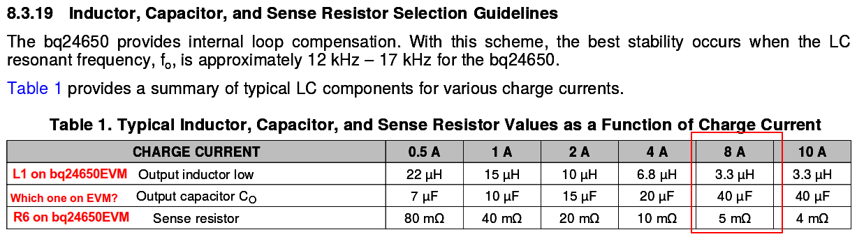
Component replacement on bq24650EVM for 8A charge current operation:


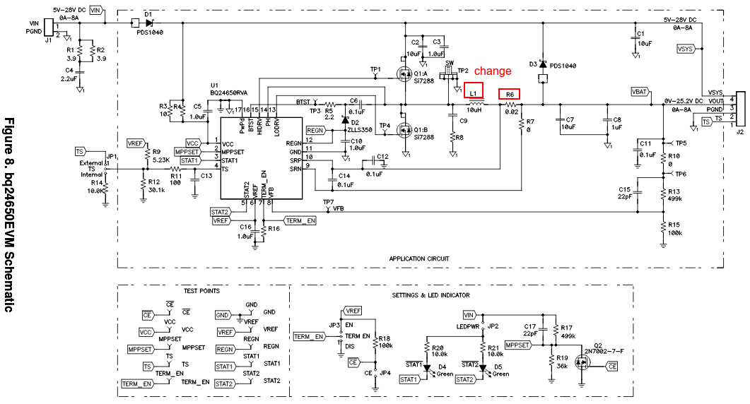
Q1. The inductor to replace on bq24650EVM for 8A operation is L1 and sense resistor is R6. But which is output capacitor C0 (as mentioned in bq24650 data sheet 8. ) in the bq24650EVM that I need to replace?
schematic of bq24650EVM:


I have the following questions, when using solar panel as input for the bq24650EVM:

Q2. Can I operate the bq24650EVM with a 150W, 8A solar panel?

Q3. Can I operate the bq24650EVM to utilise the MPPT feature of bq24650 to obtain maximum efficiency from the solar panel?

Q4. When the battery pack connected to bq24650EVM is completely charged using the solar panel input, after completion of charge does the solar power input feeds to the DC load if connected across the battery pack?


Q5. If the bq24650EVM is operated with a solar panel input, what specific protection features do I need to include in this type of set-up?

Thanks and regards!

  • Hello,

    C0 is COUT, means all the output capacity, includes C7 C8.

    8A charge current is OK, and the max VIN is 28V

    sure, you can use MPPT feature

    The output current is related to the VBAT, you can refer to P12, so if your battery voltage is above regulation voltage, there is no current.

    The charger has great protection.

    Regards

  • thanks Kerry Song,

    So for 8A operation of the bq24650EVM I will replace the following components to these new ones:

    L1: 3.3uH, 9A, 16 mOhms inductor
    R6: 0.005ohm, 1W, 1% (current sense resistor)

    I have confusing regrading C7 and C8:
    should I replace both with a 40uF, 35V capacitor or only C7?

    Thanks and regards.
  • Hello,

    Recommend use several cap for output cap, the total value is COUT.

    Regards

  • Thanks Kerry Song,

    I will keep in mind that C0 should be 40uF for 8A operation. I have now just few queries:

    Q1. I am unable to find a ceramic capacitor of 40uF, 35V. I am panning to connect several in parallel to reach an equivalent of 40uF. I hope this is not an issue and should work fine?

    Q2. The new inductor L1 required for 8A operation is of 3.3uF, 9A, rating. There are some inductors with these ratings, but are larger in size, and cannot sit in place of stock inductor. I hope to solder the new inductor with longer leads in place of stock inductor. I hope this is not an issue and should work fine?


    Thanks and regards!
  • Hello,

    For Q1, it's OK and should work fine. for Q2, please describe your question clearly. Anyway, it's OK if your inductor value, resistance value and size of L are satisfy your demand,

    Regards