This thread has been locked.

If you have a related question, please click the "Ask a related question" button in the top right corner. The newly created question will be automatically linked to this question.

BQ25895: Charge tempeture and R ILIM resistance calculation

Part Number: BQ25895
Other Parts Discussed in Thread: , BQSTUDIO

Hi

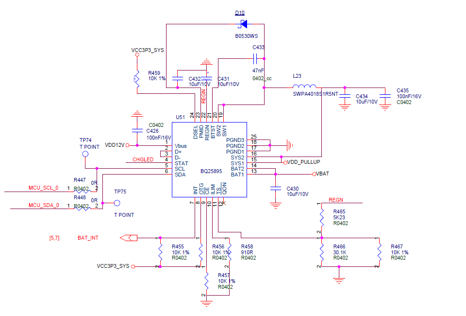
    I have a development board BQ25895EVM-664,and test it as 4.5A Charge for 8000mAh Li-lion battery,is work well, then I Design My board by BQ25895,has some issue,first my sch is this
Issue is:

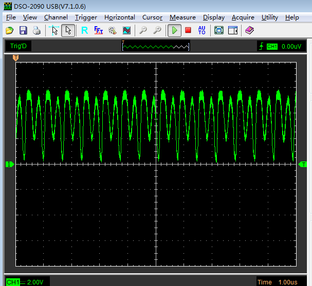
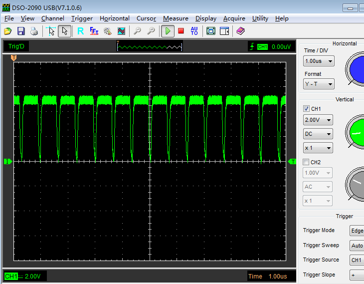
1. Demo Board Temperature most can't feel,when charge current below 3.5A,but my board is very heat,most Higher than Demo board is work at 4.5A, no matter my charge set 3.5A or 2A, i had changed same inductance as  demo,I try input voltage at 5V and 12V,is the same result, this is my board sw wave,and  this is demo's wave ,all charge current is 2.1A,I don't no what happend
2.use ev2300 debug BQ25895,wether demo board or myself board ,when i click Battery Management studio 's "Field View",Charge will stoped ,must break off input power and battery,

3.Charger current set by ILIM,how can I  calculation the resistance,such as I want set max charge current is 4.5A, the resistance value is ?

    thanks !

  • Regarding the schematic, the minimum SYS capacitance for stability is at least 10uF so please add an additional 10uF if not already somewhere else on the schematic.  Also, you can increase efficiency slightly, and therefore lower the IC's temperature, by adding a Schottky diode, anode to Ground and Cathode to SW.  This diode needs to be as close as possible to the IC.

    Regarding 1, your IC appears to oscillating into and out of thermal regulation.  is your PCB a 2-layer, 2-oz copper board?  Is the IC's exposed pad attached to bottom side ground plane using at least 5 vias?  This PCB thermal calculator described and linked to within this app note http://www.ti.com/lit/an/slua566/slua566.pdf. might be helpful.  It doesn’t have our part but if you pick a part in a similar package (e.g. RGE), you can get an estimate of board area for a given temperature rise.  Please read the appnote carefully as there are assumptions about the PCB design.  The EVM is 4-layer, 2-oz copper board with the pad via'd down to one internal layer ground plane and the bottom ground plane.  At VBUS=9V and ICHARGE=4A, the top of the IC measures 55C.  At VBUS=12V and ICHARGE=4A, the top of the IC measures 55C.

    Regarding 2, I don't understand the question.  The Field View button should only change the bqStudio screen and not perform any write to the IC.

    Regarding 3, for maximum input current = 3.25A, you can short the ILIM pin to ground.   Keep in mind that at VBUS=5V and ILIM=3.25A, the maximum output power is less than 5V*3.25A = 16.25W due to loses.  You can estimate max output power and therefore max charge current using an efficiency power balance, eff=Po/Pin=VBAT*IBAT/(5V*3.25A) where the datasheet efficiency give you an estimate of efficiency at your operating point.  For ICHARGE > 3.25A, you will need VBUS>6V.