This thread has been locked.

If you have a related question, please click the "Ask a related question" button in the top right corner. The newly created question will be automatically linked to this question.

LM3409HV: ~5 us delay on the LED current rise and fall time from the PWM2 signal.

Part Number: LM3409HV

Hi

Using the LM3409HV eval board to power 4 LEDs in a string (planning go up to 6 LEDs with up to 2A drive current). Vin power supply is 24V. 5V on 5V. VADJ is from an external adjustable supply from 0 to 1.5V. And 10 kHz 50% duty square wave 5V signal on PWM2.

No modification done on the board yet. The board comes with the shunt diming option.

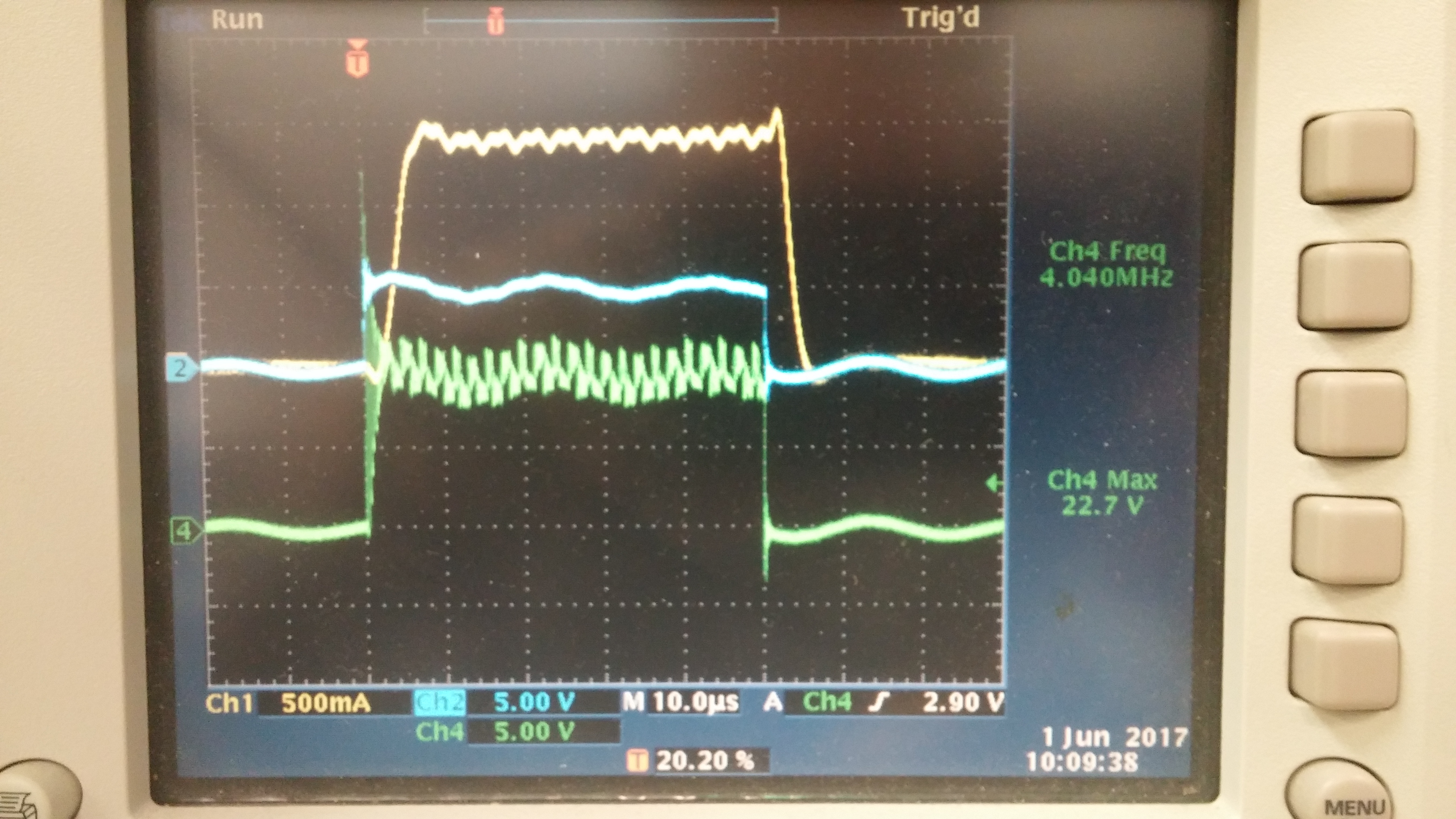
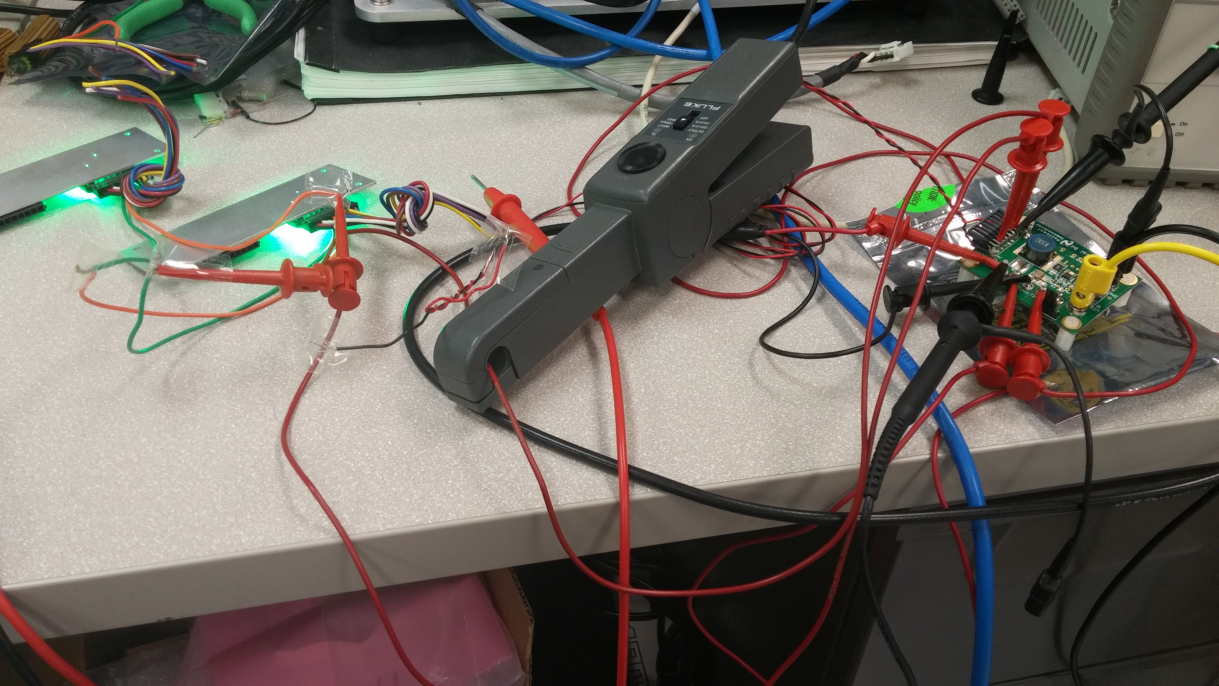
The 5us delay is from the rising edge of PWM2 to LED current reaches the high level. And ringing on VLED+ was seen during this delay time. However, about the same 5us delay was seen when LEDs were switched off. The 5us delay is from the falling edge of PWM2 to LED current goes back to almost zero. Fig. 8 in the user's guide shows very small delay (<<0.5us). The screen capture shows the signals (Yellow: LED current, Blue: PWM2 Green: VLED+). Also a picture of the setup.

www.ti.com/.../snva390d.pdf

A few things tried to isolate the problem. (1) varied the LED current from zero to max by VADJ, the delay did not change. (2) the wires connecting to the LEDs was changed from ~3 feet to ~1 foot in length, the delay did not show noticeable change. Seems like some RC or LC time constant controls the delay.

I thought It might be related to the optional parts in Fig. 5. But the switching off should be only related to the speed of Q3 per datasheet page 17.

Thank you!

FZ

  • Hello,

    I'm going to take a wild guess and say the shunt on J1 is in position 2? Is that correct?

    Honestly the best way to shunt FET dim wasn't as well understood when this EVM was developed. I'm not sure the exact reason for the EN coupling but it does indeed introduce a delay both directions and you are correct, it is formed by R4 and C9. To get rid of the delay and also to have better shunt FET dimming performance you will want to remove this and connect things a little differently. Try this:

    1. Remove R4 and C9.

    2. Place the J1 shunt in the #1 position (or a control signal with no shunt) to pull EN high.

    3. Refer to figure 5. Use the circuit for 2 off timers but connect the anode of the diode for Roff2 directly to the 5V supply.

    4. Make sure you have removed C8 or you can cause damage.

    You might need to tweak the value of Roff2 to get the best performance but this should get rid of the delays you are seeing and it will actually work better. By the way, since it usually needs to be tweaked on the bench, the point is to make the inductor (and LED without C8) current peak-to-peak ripple the same as it is with the shunt FET off. That is how you get the best shunt FET dimming performance.

    Regards,

    Clint

  • Hi Clint,

    Thank you so much for your quick response and suggestions. I am going to follow the steps and let you know the results. Need to order the diodes first for the modification.

    Thanks,
    FZ