This thread has been locked.

If you have a related question, please click the "Ask a related question" button in the top right corner. The newly created question will be automatically linked to this question.

LM5060: LM5060 / Input current oscillation during start up

Part Number: LM5060
Other Parts Discussed in Thread: CSD19536KTT, CSD19536, CSD19532KTT, CSD

Hi,

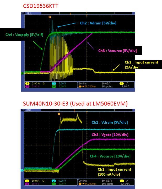
My customer is facing input current oscillation during start up on their test board. Now they are using TI's CSD19536KTT as external FET.  They tried to replace it to SUM40N10-30-E3 that is used at LM5060EVM, and then this problem is fixed as attached. So it seems it needs to take care to choose external FET. Actually CSD19536KTT has larger Qg and smaller Rds(on) compared with SUM40N10-30-E3.

Please see attached waveform and give your opinion why this behavior is happened when CSD19536KTT is used.

Best Regards,

Satoshi / Japan Disty

  • Satoshi,

    The CSD19536 has a high transconductance (delta Iout / delta Vgs) compared to the SUM40N10-30-E3. Try an RC across G-S. 1k or 2k in series with 1000pF to 5600pF. Let me know how it behaves and we can go from there.

    Brian
  • Hi Brian,

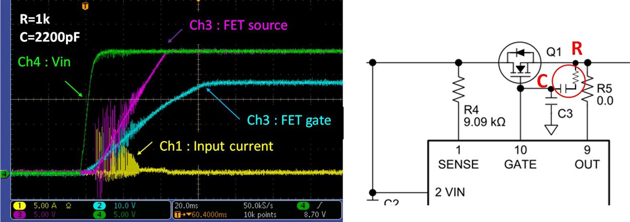
    Here is the result of waveform with adding RC across gate and source, but the input current oscillation still can be seen. They added RC as attached. Is this followed your advice?

    The waveform was measured with R=1k and C=2200pF and also they tried with R=2k, C=2200pF and R=2k, C=4400pF but the behavior was not improved. So please continue to give your comment for following question.

    1. Can you suggest other solution to improve this behavior?
    2. Can you explain the reason why the higher transconductance cause of this behavior?
    3. Do you have the guideline of limitation for transconductance to chose appropriate FET? For example, can you recommend to use CSD19532KTT (gfs=113S(typ)) for proper operation?

    Best Regards,

    Satoshi

  • Hi Brian,

    Can you give your further comment? Please let me know if you need more information.

    Best Regards,
    Satoshi
  • Satoshi,

    The high transconductance of the CSD device was what I suspected caused what looked like an instability during gate ramp, which the RC should dampen. Given the rise time, it looks like you have a gate-gnd cap installed for SS. You can also add a 10nF without a resistor g-s to see the impact. Can you provide a schematic with values indicated on it. I may have to work this on the EVM but won't be able to for several days. If you have an EVM, you can also.

    Brian
  • Hi Brian,

    I'll send you customer's schematic directly.

    Best Regards,

    Satoshi

  • Satoshi,

    Try adding a 10ohm to 30ohm gate resistor. You can try this with and without an RC gate-source.

    Brian
  • Hi Brian,

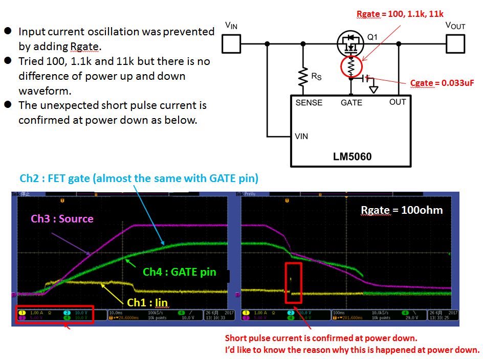
    Thank you for your advice for gate resistor. Customer tried to add 100, 1.1k and 11k as gate resistor, then they could see normal start up without oscillation at all resistors. But then they confirmed short pulse current at power down as additional behavior. So please let me ask following question when gate resistor is added.

    • What resistor value do you recommend for gate resistor? Please let me know the concern when larger value is used if the smaller value is better.
    • Can you give you opinion for the reason of short pulse current at power down, and how to prevent it?

    Best Regards,

    Satoshi

  • Hi Satoshi,

    Look below for my comments on both questions in red:

    1. What resistor value do you recommend for gate resistor? Please let me know the concern when a larger value is used if the smaller value is better.

    We usually recommend a 10ohm resistor. Exact values are fairly arbitrary. You don’t want too big or else it slows down shutdown time. You don’t want too small or else it has minimal effect. A 100ohm resistor is probably high (not recommended), and slowing down the turnoff time could violate the SOA of the FET.  

    2. Can you give you opinion for the reason of short pulse current at power down, and how to prevent it?

    I believe that when the gate is shutting down and Vgs is approaching its threshold, the output cap is providing a burst of current to the load downstream. Was the current measured from the output (source of the FET), or the input (drain of the FET)? 

  • Hi Aramis,

    I appreciate for your support. Regarding the pulse current at power down, it can be seen at output (source of the FET). So that means that this current is flowed from input to output when FET is turned off.

    Best Regards,
    Satoshi