Other Parts Discussed in Thread: CC2540, BQ25504
Hi,
I am new to this evaluation board. I would like to ask following questions.
Our setup as follows:
Input : ~1V DC source to BQ25504EVM-674
Battery : More than UV
Load : CC2540 MCU
Q1. As per BQ25504EVM user guide (page 8) Figure 5, does it means, once EVM has input power, it will start to provide power to MCU (Vstor), at the same time, starting to charge the battery (Vbat)? If that the case, will it cause unintended behaviours to MCU, due to low voltage from (Vstor) at initial start-up ?
--------------------------------------------------------------------------
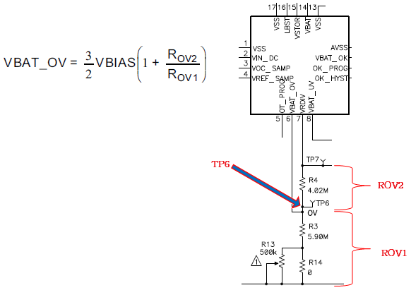
Q2. As for under voltage (UV) adjustment, we have to add variable resistor at R18 right.
However, by adding variable resistor, it will be in parallel with 0 ohm resistor (R15). Any resistor in parallel with 0 ohm resistor will be almost zero too.
So, how does it works?
--------------------------------------------------------------------------
Q3. For wireless energy harvesting application, do you have any recommended MPPT % ?
Thanks a lot.
Regards