This thread has been locked.

If you have a related question, please click the "Ask a related question" button in the top right corner. The newly created question will be automatically linked to this question.

TPS28225: TPS28225 output noise when increasing VDD above 4.5V

Part Number: TPS28225

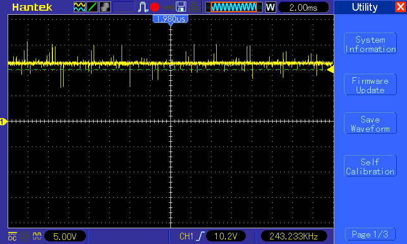
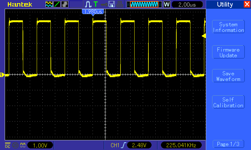
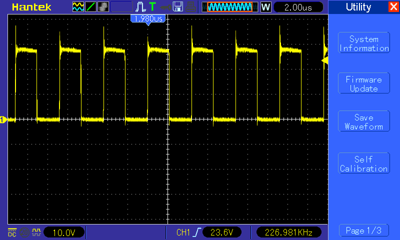
I'm am designing a dc-dc converter based on the TPS28225. When powered with VDD=4.5V the output is clean, however when increasing VDD to 5V the output voltage decreases to 5V and becomes very noisy. The fets are also dissipating a lot more heat.
These results are achieved with the following parameters:

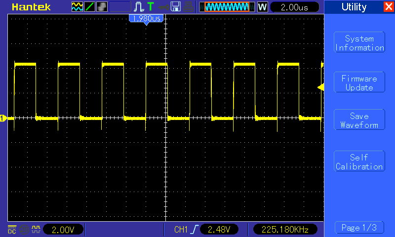
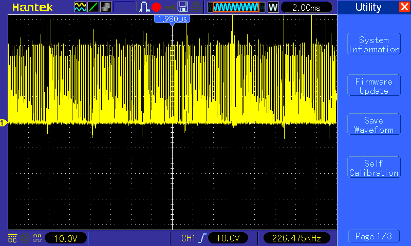
PWM: F=226kHz, D=50%, 3.4V
EN = 3.4V
Vin = 25V

I can't seem to find an explanation as to why the output gets noisy when increasing VDD. I tried using an larger bootstrap capacitor (100nF) but it didn't make any difference.
I would like to be able to use 5V to power the driver for practical reasons.
Attached are the scope images and the schematic. Any help would be apreciated.

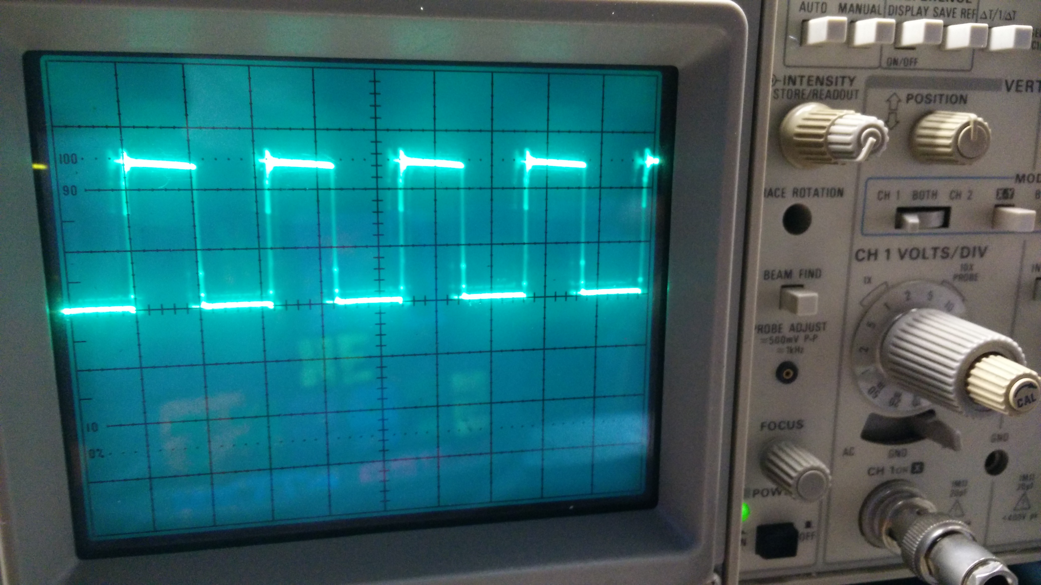
VDD=4.5V, V/div=5V S/div=10uS

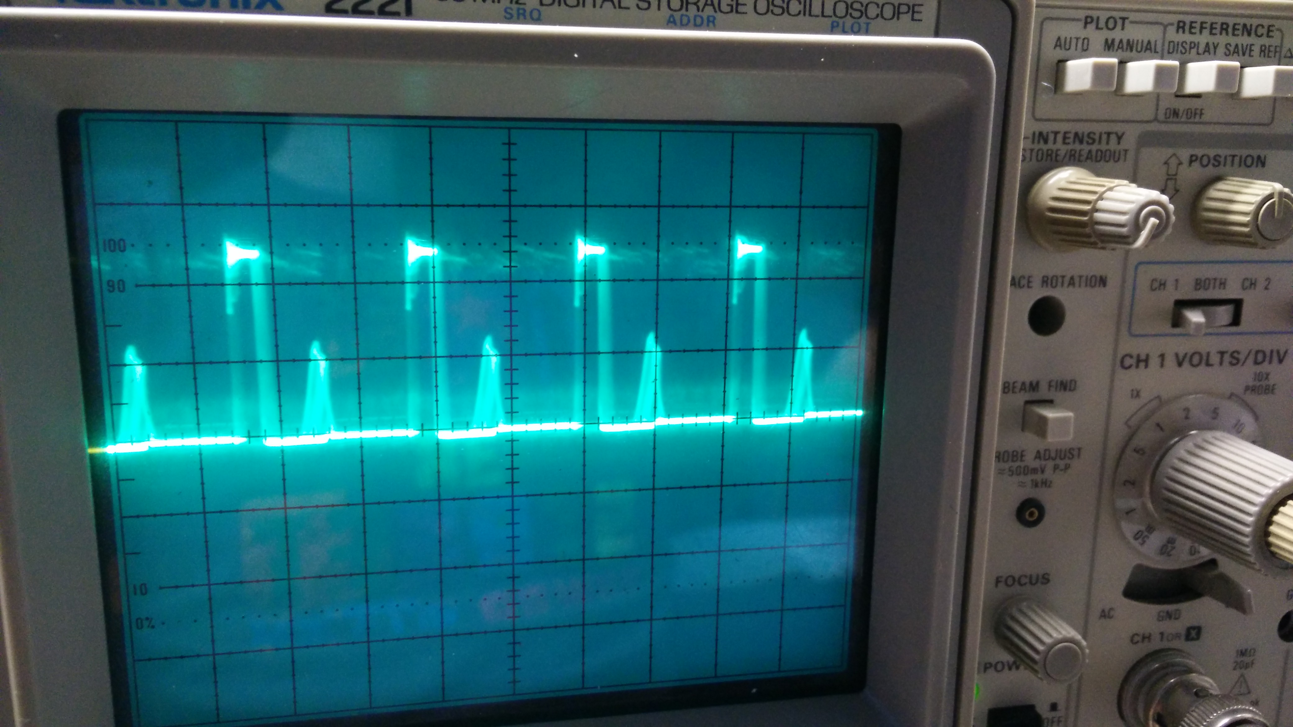
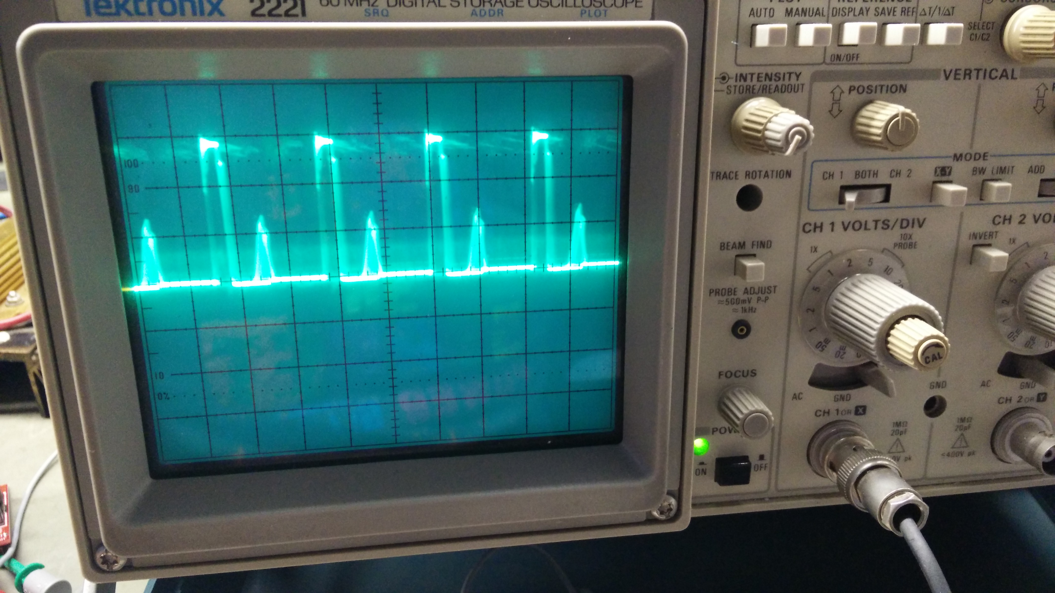
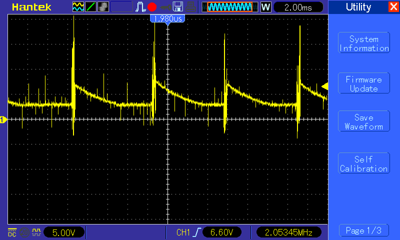
VDD=5V, V/div=5V S/div=10uS


The 3-state PWM has been disabled with a 3.3k resitor for R7.

  • Hello Timon,
    Without seeing more detailed waveforms of the driver input, driver outputs and the switch node, it is not possible to say for sure what is changes in the operation from 4.5V to 5V.
    It is likely that with 5V VDD the Mosfets switching transitions are faster and generating faster dV/dt.
    Can you review the operation at 4.5V and 5V and confirm; the controller input signal to the driver is consistent. There may be noise increase which may lead to pulse to pulse inconsistancies. Review the driver input signal with the probe ground and tip places close to the driver IC pins.
  • Hi Timon,

    Thanks for considering TI for all your needs. I am a systems engineer at TI will try to help resolve the issue.

    I could not see the waveform clearly on the second scope shot.

    Have you fabricated a fairly decently laid out PCB? Or do you have bread-board with wires?

    It is possible that board layout is not very good and you have cross conduction issue due to noise on the gate of power. MOSFET.

    It is always a good idea to have gate resistor in design. If you do not need them, then you can put 0 ohm later on.

    Generally, there should not be significant difference between 4.5V and 5V at VDD.

    You should look at LGATE, UGATE, PHASE, and BOOST pins as well (both at 4.5V and 5V).

    Did you try to change switching frequency (lower it) and observe the behavior at 5V?

    Have tried different power MOSFETs?

    How are you generating your 5V supply.

    Do you have local electrolytic capacitor on the board for your bias supply if you are using external power supply for it?

    Have you tried starting up into 5V instead of increasing from 4.5V to 5V slowly?

    Let us have some more details about the test setup and operating conditions as mentioned above and then we will move as per our findings.

    Regards,

    Ritesh

  • Ok i here are the scope images I apologize if the waveforms are hardly visible but i can't do any better with the amount of noise and shutterspeed.

    Phase VDD=4.5V, V/div=10V S/div=2uS

    Phase VDD=5V, V/div=10V S/div=2uS

    Boot VDD=4.5V, V/div=10V S/div=2uS

    Boot VDD=5V, V/div=10V S/div=2uS

    HDRV VDD=4.5V, V/div=10V S/div=2uS

    HDRV VDD=5V, V/div=10V S/div=2uS

    LDRV VDD=4.5V, V/div=2V S/div=2uS

    LDRV VDD=5V, V/div=2V S/div=2uS

    So it seems that the high drive results in the problem but what is causing it?
    I noticed a lot of noise on both VDD, PWM and ENABLE at 5V. For VDD, ENABLE and VIN i'm using seperate bench supplies.
    I'm testing the schematic on a PCB with a seperate ground for signal wires that is connected to PGND at a single point.
    Here is the PCB layout.

  • Hi Timon,

    VDD seem to be clean at 5V to me as in LO waveform you provided the high level is very clean.

    Transistor reference designator in schematic and layout does not seem to match.

    Did you replace the part with a fresh part to see if the issue is repeatable?

    Increase the bootstrap capacitor to 0.47uF/25V.

    It seems that something on high side breaks down when you go from 4.5V to 5V.

    May be there is a bad soldering or damaged part on the board.

    Please take PWM waveform as well, but looking at LO waveform, I believe PWM signal is clean as well.

    You can also try to supply only the driver (no Vin or bus voltage) and see if you observe the same behavior or different.

    There is nothing in the part that will truncate the HO pulse the way it is doing when you go from 4.5V to 5V.

    Did you try to go higher than 5V and did you try different voltage between 4.5V and 5V?

    Please make sure that your grounding is what it should be.

    Let us do more investigation.to find out what is happening here.

    Regards,

    Ritesh

  • Please excuse me for the late reply.
    The driver broke and it took a fet with it so the next driver broke too.
    So i had to wait for new parts.

    Anyway, the problem has become somewhat worse with the new driver.
    The behaviour is the same but at lower voltage levels. Vdd needs to be 4V now for a good output. The voltage drop at the output occurs at 4.5V now.
    I also tried replacing Cboot with 1uF 50v ceramic but no change.
    I got my hands on a digital scope so the waveforms are better visible now.
    Without supply voltage to the fets highdrive seems to function properly.

    Output VDD=4V


    Output VDD=5V Basicly the same but lower voltage and all over the place so I changed s/div Note the frequency of the waveform is roughly 1/5 of the pwm frequency.

    Output VDD=4V s/div same as last waveform


    Hdrive Vdd=4V No supply voltage on fets.


    Hdrive Vdd=5V No supply voltage on fets.

    Hdrive Vdd=4V


    Hdrive Vdd=5V What's causing the irregular waveform?

    Hdrive Vdd=5V Note s/div

    Hdrive Vdd=4V Note s/div

    Boot Vdd= 5V


    Pwm VDD=5V

  • Hello Timon,

    This is Richard Herring  Application Engineer with TI. I replied to your earlier post and have reviewed the conversations with you and Ritesh.

    In comparing the scope plots of Hdrive with no input voltage on the MOSFET's it does appear that the turn off is sharper when VDD is 5V as compared to 4V. You also mentioned that VDD, EN and PWM seem to have more noise at the higher level VDD level of 5V.

    I see in the schematic you have 3.5K resistance to ground which I assume means you do not need the 3-state function.

    As Ritesh mentioned, there is nothing in the IC that should truncate the high side output with the VDD change from 4V to 5V. I am thinking there is increased noise on one or more of the IC pins at the higher VDD, since the driver has more drive capability at higher VDD.

    Can you try making sure the 3 state input is disabled, and lower the PWM to ground resistor to 3K or less?

    Also since the EN pull up is sourced from a lab supply, can you  add a filter capacitor from EN pin to ground?

    As Ritesh suggested, ensure the ground reference of the PWM input and external power supplies is referenced well to the IC ground at the VDD capacitor connection.

    Regards

    Richard

  • I have been trying everything i can think of.

    I tried pulling the pwm down with 2.4k and 1k.
    Added a 1000uF elco to Cin as close as possible over the drain of the high side mosfet and source of the low side mosfet.
    220nF on the enable pin.
    Tried 10uF and 560uF for the drivers decoupling capacitor.
    Removed the original Cin capacitors.
    Removed the Cout capacitors, tried different ones and moving them closer to the inductor and source of the low side driver.
    Tried several inductors with lower srf to decreasing the ground noise.
    Adding gate resistors to the highdrive fet. (10, 33 and 100ohm the fet and driver break at 100 ohm for some reason)

    None of the made any significant change. The Output still dropsout still occurs and always seems to happen (after replacing driver and fets) at around 4.65V (a little above 4.5 and abruptly at 4.65V).
    Adding capacitance to Cin and using inductors with a lower srf. Significantly improved the noise level but there were no significant changes in the dropout level.

    Everybody thanks for your help, any suggestions are welcome.