Other Parts Discussed in Thread: BQ28Z610, BQ24295, BQ27510, BQSTUDIO,
I am trying to configure the BQ27441-G1A for a new larger battery (2900 mAh). I have previously had this working with a smaller battery using the default settings.
Based on the quick start guide, it appears that I only need to change 4 register values for this to work.
I followed the pseudo code example in the TRM, section 3.1 (pg 14) "Data Memory Parameter Update Example", to create a bash script (attached) to update these registers.
I have set the 4 parameters using this bash script:
Design Capacity = 2900 mAh
Design Energy = (Design Capacity) * 3.7 = 10,700 mWh
Terminate Voltage = 3200 mV
Taper Rate = (Design Capacity) / (.1 * (Taper Current)) = 98 (.1 Hr rate)
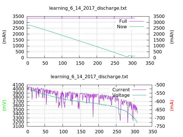
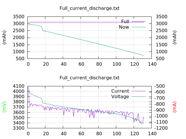
I tested the larger battery with the default values in the BQ27441-G1A, and with the updated values. I am now having problems with the battery gauge accurately reporting the battery percentage. In our tests the battery is jumping from 92% to 100% charged, and then during discharge the battery is dying while still reporting between 17 - 30 percent remaining.
Is there another step to programming the fuel gauge that I missed?
#!/system/bin/sh

#######
#README
#######
#
# Script to modifiy the registers of the TI BQ27441-G1A battery gauge for a new battery configuration
#
# This script is intended to overwrite the default values of 4 important configuration parameters.
# These parameters are:
# Design Capacity - Nominal battery capacity printed on the battery label, or found in the battery data sheet. (in mAh)
# Design Energy - Is equal to Design Capacity x 3.7 for bq27441-G1A
# Terminate Voltage - The minimum operating voltage of your system. This is the target where the gauge typically reports 0% capacity. (mV)
# Taper Rate - Should be set to the current threshold in mA below which your charger IC is set to stop charging once it considers the battery to be full. (Taper Rate = Design Capacity / (0.1 * Taper Current))
#
# Based largely on a pseudo code example in Section 3.1, pg 14 of the TRM Rev. A (http://www.ti.com/lit/ug/sluuac9a/sluuac9a.pdf)
#

#
# See Criticallink Internal Redmine issue #12557
#
# Jarrett Pischera 6/7/2017
# Jpischera@criticallink.com
#

###################################################################
# User Modifiable Device Configuration Parameters (Decimal Numbers)
###################################################################

# Design Capacity in mAh
USER_Design_Capacity=2900
#Terminate_Voltage in mV
USER_Terminate_Voltage=3200
# Taper Current in mA
USER_Taper_Current=256

#######################################
# Device configuration parameters (hex)
#######################################

# Design capacity convert to hex and calculate MSB and LSB
Design_Capacity=$(printf 0x%X\\n $USER_Design_Capacity)
Design_Capacity_LSB=$(printf 0x%X\\n $(($Design_Capacity % 0x100)))
Design_Capacity_MSB=$(printf 0x%X\\n $(( ($Design_Capacity - $Design_Capacity_LSB) / 256)))

# Design Energy is directly dipendent on the Design Capacity. The factor of 3.7 is from the TRM for the -G1A chips
temp_DE1=$(($Design_Capacity * 3))
temp_DE2=$((($Design_Capacity * 7) / 10 ))
temp_DE3=$(($temp_DE1 + $temp_DE2))
Design_Energy=$(printf 0x%X\\n $temp_DE3)
Design_Energy_LSB=$(printf 0x%X\\n $(($Design_Energy % 0x100)))
Design_Energy_MSB=$(printf 0x%X\\n $(( ($Design_Energy - $Design_Energy_LSB) / 256)))

# The terminate voltage in mV (hex)
Terminate_Voltage=$(printf 0x%X\\n $USER_Terminate_Voltage)
Terminate_Voltage_LSB=$(printf 0x%X\\n $(($Terminate_Voltage % 0x100)))
Terminate_Voltage_MSB=$(printf 0x%X\\n $(( ($Terminate_Voltage - $Terminate_Voltage_LSB) / 256)))

# The taper rate, assuming that the charger taper current is 256 mA. Following the formula above.
Taper_Current=$USER_Taper_Current
Taper_Current_15=$(( ($Taper_Current + ( ($Taper_Current * 15 ) / 100 ) )))
Taper_Rate=$(printf 0x%X\\n $((($Design_Capacity * 10 ) / $Taper_Current_15)))
Taper_Rate_LSB=$(printf 0x%X\\n $(($Taper_Rate % 0x100)))
Taper_Rate_MSB=$(printf 0x%X\\n $(( ($Taper_Rate - $Taper_Rate_LSB) / 256)))

#################
# I2C Information
#################
i2c_bus=0x0
i2c_chip_addr=0x55

#################################
# Register Modification Procedure
#################################

# UNSEAL the device by writing Control() (0x00 and 0x01) with the UNSEAL key 0x8000. ie Control(0x8000)
i2cset -y -f $i2c_bus $i2c_chip_addr 0x00 0x00
i2cset -y -f $i2c_bus $i2c_chip_addr 0x01 0x80
i2cset -y -f $i2c_bus $i2c_chip_addr 0x00 0x00
i2cset -y -f $i2c_bus $i2c_chip_addr 0x01 0x80

# Enter CONFIG UPDATE Mode SET_CFGUPDATE. ie Control(0x0013)
i2cset -y -f $i2c_bus $i2c_chip_addr 0x00 0x13
i2cset -y -f $i2c_bus $i2c_chip_addr 0x01 0x00

# Confirm that CFGUPDATE mode has been set
sleep 1.5
echo "Confirm bit 4 is high for CFGUPDATE:"
i2cget -y -f $i2c_bus $i2c_chip_addr 0x06

# Ensure block data memory control by writing 0x00 using the BlockDataControl() command
i2cset -y -f $i2c_bus $i2c_chip_addr 0x61 0x00

# Access the State subclass (0x52), which contains the configuration parameters, using the DataBlockClass() command
i2cset -y -f $i2c_bus $i2c_chip_addr 0x3E 0x52

# Write the block offset location using DataBlock() command. For data 0 to 31 use 0x00, for data 32-41 use 0x01
i2cset -y -f $i2c_bus $i2c_chip_addr 0x3F 0x00

# Read the 1-byte checksum using the BlockDataChecksum() command
old_chksum=$(i2cget -y -f $i2c_bus $i2c_chip_addr 0x60)

# Read the Design Capacity bytes staring at 0x4A (offset = 10; from TRM)
old_Design_Capacity_MSB=$(i2cget -y -f $i2c_bus $i2c_chip_addr 0x4A)
old_Design_Capacity_LSB=$(i2cget -y -f $i2c_bus $i2c_chip_addr 0x4B)

# Read the Design Energy bytes starting at 0x4C (offset = 12; from TRM)
old_Design_Energy_MSB=$(i2cget -y -f $i2c_bus $i2c_chip_addr 0x4C)
old_Design_Energy_LSB=$(i2cget -y -f $i2c_bus $i2c_chip_addr 0x4D)

# Read the old Terminate Voltage starting at 0x50 (offset = 16; from TRM)
old_Terminate_Voltage_MSB=$(i2cget -y -f $i2c_bus $i2c_chip_addr 0x50)
old_Terminate_Voltage_LSB=$(i2cget -y -f $i2c_bus $i2c_chip_addr 0x51)

# Read the old Taper Rate starting at 0x5B (offset = 27; from TRM)
old_Taper_Rate_MSB=$(i2cget -y -f $i2c_bus $i2c_chip_addr 0x5B)
old_Taper_Rate_LSB=$(i2cget -y -f $i2c_bus $i2c_chip_addr 0x5C)

# Write the new Design Capacity
i2cset -y -f $i2c_bus $i2c_chip_addr 0x4A $Design_Capacity_MSB
i2cset -y -f $i2c_bus $i2c_chip_addr 0x4B $Design_Capacity_LSB

# Write the new Design Energy
i2cset -y -f $i2c_bus $i2c_chip_addr 0x4C $Design_Energy_MSB
i2cset -y -f $i2c_bus $i2c_chip_addr 0x4D $Design_Energy_LSB

# Write the new Terminate Voltage
i2cset -y -f $i2c_bus $i2c_chip_addr 0x50 $Terminate_Voltage_MSB
i2cset -y -f $i2c_bus $i2c_chip_addr 0x51 $Terminate_Voltage_LSB

# Write the new Taper Rate
i2cset -y -f $i2c_bus $i2c_chip_addr 0x5B $Taper_Rate_MSB
i2cset -y -f $i2c_bus $i2c_chip_addr 0x5C $Taper_Rate_LSB

# DEBUG Read the changes to make sure they worked
echo "the old MSB and LSB of the Design Capacity, read from the register are:"
echo $old_Design_Capacity_MSB
echo $old_Design_Capacity_LSB
echo "MSB and LSB of the Design Capacity, read from the register, should be 0x0B and 0xB8"
i2cget -y -f $i2c_bus $i2c_chip_addr 0x4A
i2cget -y -f $i2c_bus $i2c_chip_addr 0x4B

echo " "

echo "The old MSB and LSB of the Design Energy, read from the register are:"
echo $old_Design_Energy_MSB
echo $old_Design_Energy_LSB
echo "MSB and LSB of the Design Energy, read from the register: "
i2cget -y -f $i2c_bus $i2c_chip_addr 0x4C
i2cget -y -f $i2c_bus $i2c_chip_addr 0x4D

echo " "

echo "The old MSB and LSB of the Terminate Voltage, read from the register are:"
echo $old_Terminate_Voltage_MSB
echo $old_Terminate_Voltage_LSB
echo "MSB and LSB of the Terminate Voltage, read from the register:"
i2cget -y -f $i2c_bus $i2c_chip_addr 0x50
i2cget -y -f $i2c_bus $i2c_chip_addr 0x51

echo " "

echo "The old MSB and LSB of the Taper Rate, read from the register are: "
echo $old_Taper_Rate_MSB
echo $old_Taper_Rate_LSB
echo "MSB and LSB of the Taper Rate, read from the register:"
i2cget -y -f $i2c_bus $i2c_chip_addr 0x5B
i2cget -y -f $i2c_bus $i2c_chip_addr 0x5C

echo " "

# Calculate the new Checksum
#	 The maxvar variable deals with the issue of taking the modulus of a negative number in bash
#	 (number of bytes changed * 0x100) + 0xff
maxvar=$(((0x10 * 0x100) + 0xff))
temp_var1=$((($maxvar - $old_chksum - $old_Design_Capacity_MSB - $old_Design_Capacity_LSB - $old_Design_Energy_MSB - $old_Design_Energy_LSB - $old_Terminate_Voltage_MSB - $old_Terminate_Voltage_LSB - $old_Taper_Rate_MSB - $old_Taper_Rate_LSB) % 0x100))
temp_var2=$((($temp_var1 + $Design_Capacity_MSB + $Design_Capacity_LSB + $Design_Energy_MSB + $Design_Energy_LSB + $Terminate_Voltage_MSB + $Terminate_Voltage_LSB + $Taper_Rate_MSB + $Taper_Rate_LSB) % 0x100))
dec_chksum=$((0xff - $temp_var2))
new_chksum=$(printf 0x%X\\n $dec_chksum)

# Write the new Checksum to BlockDataChecksum()
i2cset -y -f $i2c_bus $i2c_chip_addr 0x60 $new_chksum

# DEBUG Read the changes to the checksum ot make sure they worked
echo "The old checksum was:"
echo $old_chksum
echo "The new calculated checksum is:"
echo $new_chksum
echo "Read the saved checksum from the register"
i2cget -y -f $i2c_bus $i2c_chip_addr 0x60

# Exit CFGUPDATE
i2cset -y -f $i2c_bus $i2c_chip_addr 0x00 0x42
i2cset -y -f $i2c_bus $i2c_chip_addr 0x01 0x00

# Confirm that CFGUPDATE had been exited by polling Flags() register until bit 4 cleared
sleep 1.5
echo "Confirm bit 4 is low, CFGUPDATE has been exited:"
i2cget -y -f $i2c_bus $i2c_chip_addr 0x06

# Reseal the device
i2cset -y -f $i2c_bus $i2c_chip_addr 0x00 0x20
i2cset -y -f $i2c_bus $i2c_chip_addr 0x01 0x00