Dear Colleagues of TI,
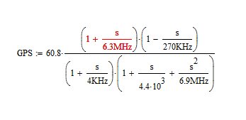
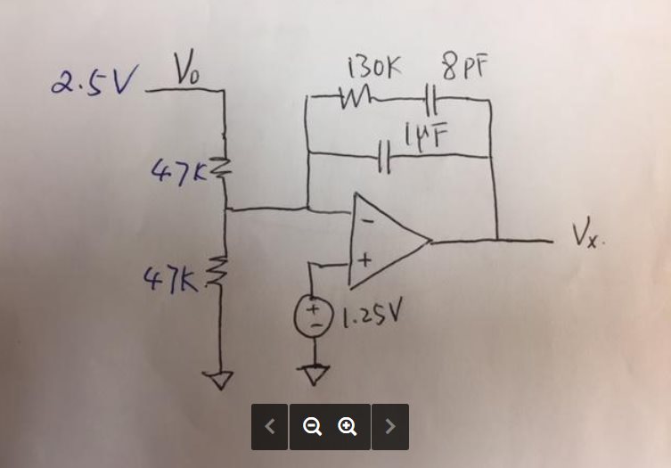
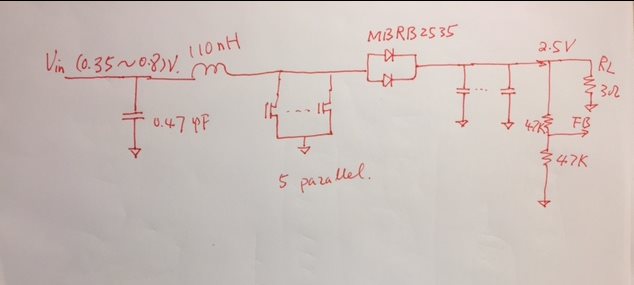
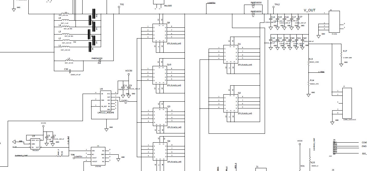
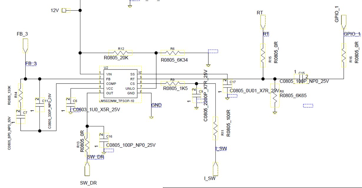
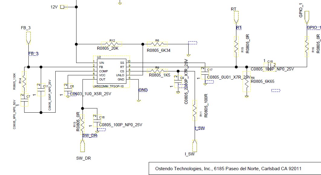
TI's specification of LM5022 has detail described the loop compensation. I used the same Methodology by MathCad and then I got the compensation circuit. I used the concluded calculation to design the actual boost circuit. But in lab test, I found when input voltage in range of 0.4V to 0.6V, the output is only 1.2V about 50% of target voltage 2.5V. If I can improve to input voltage to 0.8V or above, the output voltage can reach to 2.5V. I would like to know my control loop is corrective?
Please see attached.
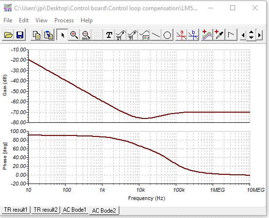
From the Bode Plot, I could not figure out the Gain and Phase Margin.


