This thread has been locked.

If you have a related question, please click the "Ask a related question" button in the top right corner. The newly created question will be automatically linked to this question.

LM25010: LM25010 instability

Part Number: LM25010

I have some serious frequency jitter in the LM25010 control.

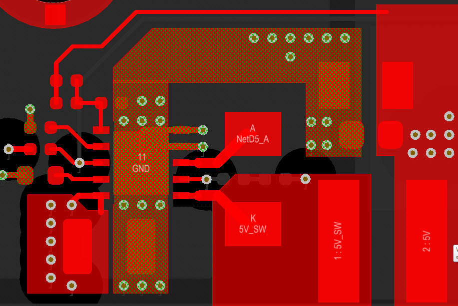
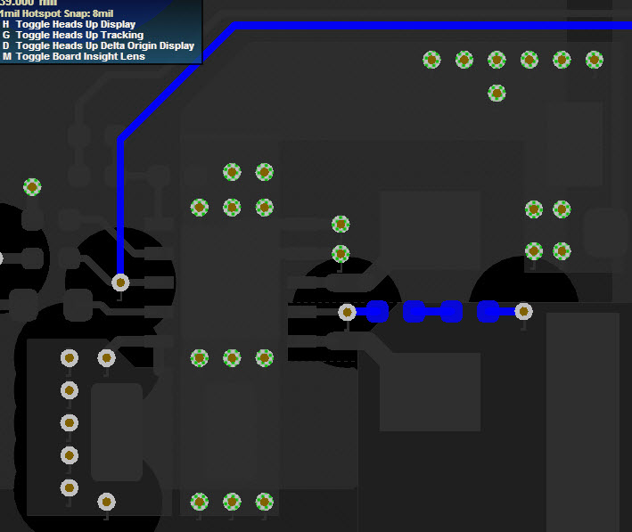
Design is attached. All my prototypes (3) have the same problem.

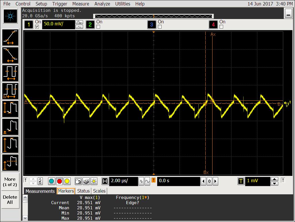
On-time matches what is set by the resistor at the Ron pin but the frequency keeps sweeping.

Vin= 13V with about 50mVpp noise (F=290kHz, another nearby power supply is to blame for that noise).

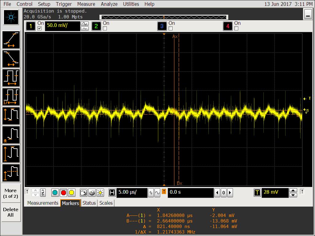
 I have attached 2 waveforms, one for the switching node and the other for the feedback (ac coupled).

At that zoom level, it may appear like only pulses are missing but measuring the off-time for nearby pulses reveals that it wanders in the 500-600ns range.

That looks like an instability issue but as there is no compensation pin available to tune the loop, I am kinda stuck...

 Anyone has any idea on how to debug this one?

Thanks

  • Hello,
    Component values shown on your schematic look properly calculated.
    Could you please share your layout?
    Regards
    Brani
  • Here you go!  I know that the output caps would be better located below the inductor but I doubt this is the cause.

    By the way, turn-on/off edges are "clean" using 15ohms gate resistor.  About 1V ringing for 12V input at 0.8A out.

  • Please check RFBB, its too Large at 10k.  This should be mR's to provide 25mV of ripple at the FB node.  Please check datasheet for designing type II ripple injection, the issue should go away.

    Hope this helps?

  • It does help.

    Indeed, ripple appeared not to be enough.

    I re-read both datasheet and snva166a app note and applied the type 3 patch (200k, 680pF and 10nF) so to keep the lowest output ripple possible.

    Double strikes vanished but there is still around 30kHz jitter.

    See FB pin (AC couple BW limited) and switching node snapshots below (Vin = 10.5V, Vout=5V Iout=0.5A).

    Is there anything more I can do?

    Thanks!

  • I typically expect a little Jitter with COT control Architectures compared to Current mode or Voltage mode control, which is fixed frequency and uses an Error amplifier with a BW much lower in frequency.

    It’s hard to say if yours jitter is excessive?  If this is worst case jitter you are seeing, check the resulting ripple for a final decision on if this is acceptable to you?  Looking at your Vout ripple scope shot, it look good to me?  Again it’s difficult to say with a snap shot of the scope plot.


    Ultimately its layout dependent, your feedback resistors should be very close to the IC and also the Ron resistor should be close to the Ron pin.  Also suggest using a shielded core inductor if you are not using one currently.  Placing an RC snubber from Switch to Ground may also help as well as placing a resistor in series with the Boot Cap to slow down the switch transitions?  One other thing to try, is placing a small 10pF/22pF cap from FB pin to Gnd. 


    Hope this helps?

  • I may consider that jitter as "free" spread-spectrum.

    Thanks for your comments!