This thread has been locked.

If you have a related question, please click the "Ask a related question" button in the top right corner. The newly created question will be automatically linked to this question.

LM25118: Disturbance and noise problems at the feedback-pin

Part Number: LM25118

Hi,

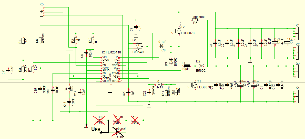
im try to develop an buck-boost-converter with a variable output voltage. I have a fix input of 17 V and the output has to change from round about 10 V to 30 V.

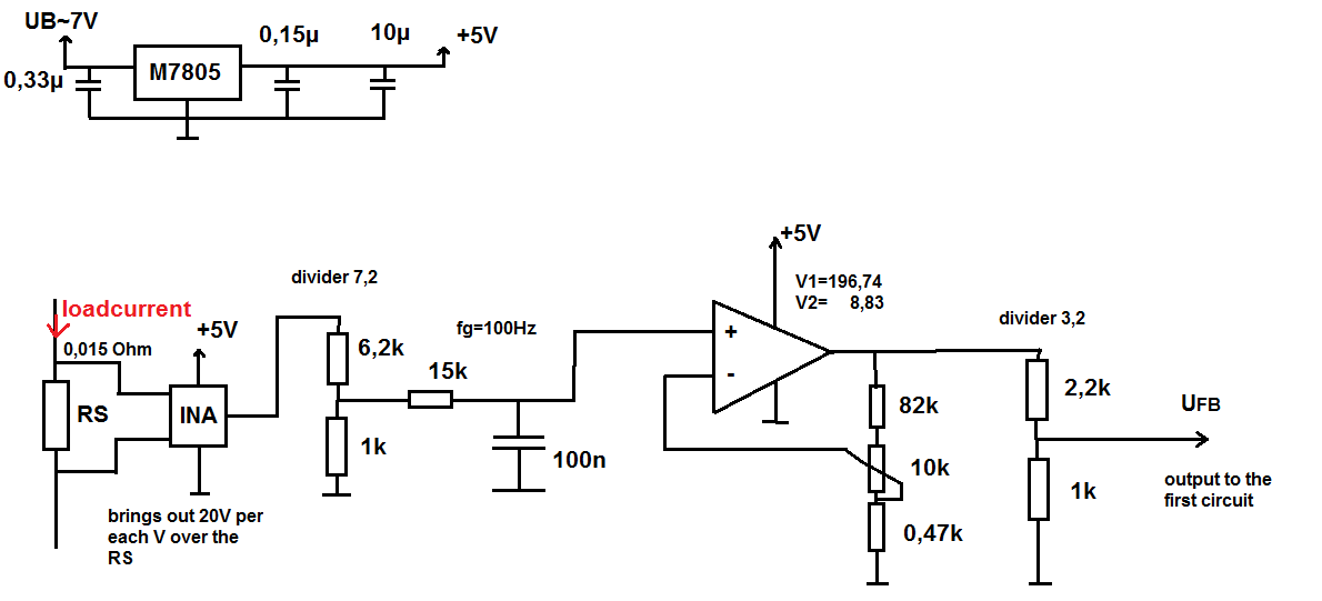
To desinge this circuit im using the LM25118. For my first testings i designed a circuit just as it was said in the datasheed. My idea is to controll the output over the voltage of the feedback-pin. For that i have a second circuit that measures  the load current of the output. The  circuit has an non inverting aplifiere on. With an changeable resistor im able to change the amplifie and so the proportion of current to output of my circuit. The internel controlling circuit of the LM25118 trys to hold the voltage of the feedback-pin constant. If im changing now the amplifie in my second circuit, the output of the LM25118 will rise or fall to change the current and hold the feedback voltage constant.

In the theory is everything wroking fin, but i have large problem with dicturbance at the feedback-pin. The output of the LM25118 is changing but the feedbackvoltage dose not stay constant. I think this happens, becuae of noise voltages. I have connected my both circuits over an 15 cm long wire. I think this wire works like an antenna. Now im not sure if this problem will go away when i design a new circuit with all components on it, so there is no long wire anymore.

Did someone had similar problems or some idears that could help me to solve my problem?

Im thankfull for every answer.

Daniel

  • Hi Daniel,

    Typically the output voltage is changed by sourcing and sinking current to the feedback pin. The feedback voltage should always be 1.23V. By sourcing and sinking current the effective resistance of the lower feedback resistor is changed. Please post your schematic and I can help review the feedback section. The long wires might be a problem, I would suggest using shorter wires.

    Thanks,

    Garrett
  • Hello Garret,

    thank you for your answer.
    I posted my schematic.

    Daniel
  • Hi,
    has somebody else an idear or suggestion how to fix my problem.
    Im still working on it, so im happy for every answer.

    Daniel
  • Hi Daniel,

    Looking at your schematic I'm not quite sure what is trying to be accomplished. Why are you using the current sense resistor to set the output voltage? Usually something like the diagram below would be used to change the output voltage dynamically.

    Thanks,

    Garrett

  • Hello Gerret,

    thank you for you answer.
    The idear is that the change of the output voltage dependce on the output current. Actually i want to rise the output and controll the current and not the voltage. The INA unit measures the voltage over the current sense resistor. This voltage gets amplified and put on the feedback pin.

    Why do you use an PWM?
    Why is RFB_1 needed, when you have an voltage at V1?
    Do you have sizes for the elements?

    Thanks,

    Daniel
  • Hey Gerret,
    i tryed out your idear. I used an anlaog-signal instead of the PWM-signal. It is nearly working fine but the feedback voltage drops at some point and im not able to change the output as hard/wide as i wish.
    Do i have to use an PWM? I mean, after the lowpass it should be nearly the same as an analogsignal.
    Do you have tips for the sizes of the emelents? Should the impedance of feedback voltage devider be a lot higher then the impedance of R1, R2 and C1?
    If you have one more tip, it would be realy helpfull.

    Thanks,

    Daniel