This thread has been locked.

If you have a related question, please click the "Ask a related question" button in the top right corner. The newly created question will be automatically linked to this question.

LM3445-120VFLBK: About LM3445 Application Question

Part Number: LM3445-120VFLBK

Hi sir,

My customer use LM3445, but have some question need you help. thanks.

1. May I know LM3445-120VFLBK can implement constant current ?

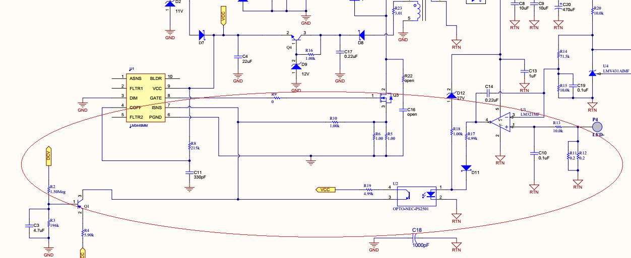
2. May I know Q1, U3, U2 function of PMP7753? for constant current?

3. Could you help provide dimming decoder circuit, controls the DIM pin level of the LEDs?

  • Hello,

    1) This is setup to regulate current with opto-coupler feedback R11 and R12 sense the LED current, U4 is the reference for the error amplifier.

    2) U3 is the error amplifier, U2 is an opto-coupler to transfer the feedback signal to the primary side across the isolation boundary, this is the feedback for constant current. Q1 appears to be a circuit for dimming, it will pull up on the Isns when the average input voltage drops but the error amplifier U3 will compensate to regulate current measured from R11, and R12 for some of that.

    3) I believe the circuit at Q1 controls dimming. If the input average voltage is high that circuit does not pull up on Isns. As the average input voltage drops it starts pulling on Isns reducing current, however the error amplifier will correct for it at first as far as it will be able to.

    It would be better to know what the customer is looking for regarding their project. There are better circuits that we have available. There is an isolated EVM using the LM3445, AN-2034, and other parts such as the LM3447 to look at if isolated is needed.

    Thanks,
  • Hi Sir,

    Thanks for your response.
    I use generator provide 3V/1k/50% duty for DIM pin. why output current no response?

    Wen
  • Hello,

    Which circuit are you using?  FLTR1 needs to be pulled high to use DIM as an input.  FLTR2 should have a capacitor across it as well. 

    Regards,

  • Dear Sir,

    Test by AN-2034 LM3445 -120VAC.

    Looks schematic already FLTR1 pulled high and FLTR2 use C connected to GND.

  • Hello,

    It needs to be pulled above 4.9 volts to allow the DIM pin to be an input.  Remove R9 and tie FLTR1 to VCC.

    The block diagram in the datasheet shows the internal functions on the IC.  Below is the Pin description, read FLTR1 description:

    Thanks,