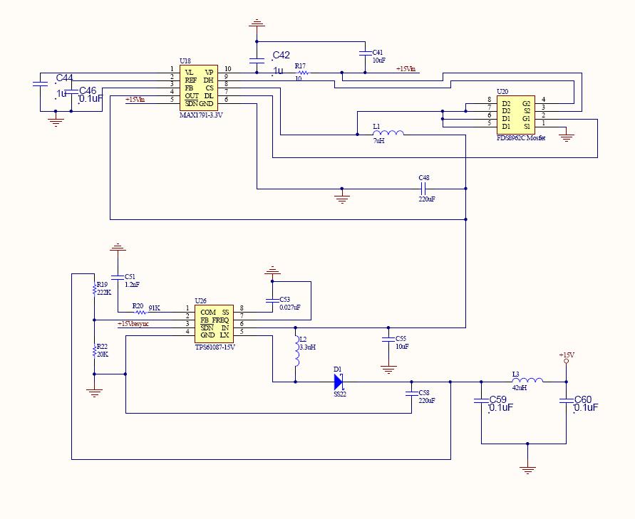
My design is based on figure 14 of TPS61087 datasheet and the input voltage is 3.3V
But TPS61087 can't generate 15V output, only 10V is generated.
Please help ASAP.
Thank you so much.
My design is based on figure 14 of TPS61087 datasheet and the input voltage is 3.3V
But TPS61087 can't generate 15V output, only 10V is generated.
Please help ASAP.
Thank you so much.