This thread has been locked.

If you have a related question, please click the "Ask a related question" button in the top right corner. The newly created question will be automatically linked to this question.

LM5122: Strobe pulse gets down

Part Number: LM5122

I have the following circuit, different for the one I post before. The idea is to gets up the Voltage from 12V to 15 V and then use a pwm signal to gets a 15 V pulsed output:

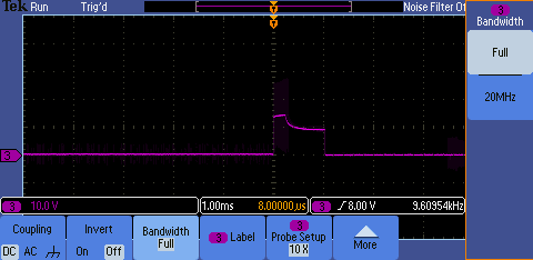
I have found a more or less correct signal when there is no load applied(15 V applied with no load).

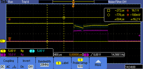
But when I connect the load (a string of leds), the pulse gets down and doesnt mantain 15 V constant, and goes down to 12 V. So the leds doesnt mantain the light intensity. Also, the  pulse has a lot of noise( the noise is seen looking live to the osciloscope, im sorryI can not show it in the image).

Some ideas what should I test ? I am not worried about the noise, It will be longer or not to fix it, but I am totally mess up with the pulse. I have no idea of what is happened. 

  • I forgot to say that pink line is corresponding with SAL1
  • Hi Ramiro,

    I think the noise that you are seeing on the output voltage is due to the way that you are probing the output voltage. Is the ground lead of the probe short? To help reduce high frequency noise the ground loop should be short. Here is a blog post talking about proper probing techniques.

    One item to check is to make sure that the device is not current limiting when the LEDs are connected to the output voltage. This would cause the output voltage to sag like the waveform indicates. What is the maximum output current that is needed to supply the LEDs?

    Thanks,

    Garrett

  • Thank you very much Garret.

    Limiting the bandwidth of the probe noise disappear so I guess it was switching noise. I will take a look into the blog.

    Regarding second question, This circuit pulsed just a lonely led, and 2 A (regarding I-V curves, it is not easy to measure I) but some of the theoretical I-V curves sometimes are not accuracy, so maybe we are talking about 2-3 A .
  • Hi again:

    I have try to see if the Lm is limiting the current in someway.

    First I have test Voltage in CSN and CSP. It seems that there is no more than  75 mv, but im not sure because I have not enough resolution . But I have seen this voltage waveform in CSN and CSP: maybe this is a clue, it seems that here is an input voltaje drop when the pulse gets high (blue line (CSN) is below yellow line (CSP). Pink is voltaje output

    Finally I ground RES directly, to see if Hicupp mode was the problema, but the behaviour is the same.

    SO I  am still confused

    Anyone can help?

    Thanks and best regards

  • Hi Ramiro,

    Are you probing the output voltage marked VOUT on the schematic? Also the pinks signal above doesn't match the same shape the you should previously for the output voltage.

    -Garrett
  • In fact, Pink os SAL1, which is the voltaje aplied yo the led.

    Youre right, the frame captured in the osciloscop seems diferent. But Pink signal is " flickering" allí the time. What you see in "real live view" is the first image, but flickering. Some few pulses strobes correctly,most not. Then, this image is one of the few correct pulses. But normaly what you ser is the first image, with the signal going down in the moment you see a gap in Pink signal un the second image