


Hello All,
I'm setting up a PFC using the UCC28180 for universal input, 400Vout 3.5kW operation. But before doing so I wanted to test the controller at a lower voltage. To do so, I've modifie feedback elements and running at 30V DC input and 100V DC out. After steady state output voltage is achieved, the controlled applies minimum duty cycle. However, I see a large amount of oscillation across the Drain-source terminals of the FET. Further to this, I added a small resistor of 4k to the output. This reduced the oscillations as shown in Figure below. I am trying to understand the reason for these oscillations and how I can control them as I ramp up the voltage later.
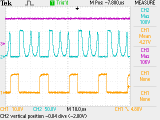
CH1: Gate signal to PFC FET; CH2: FET Drain-Source voltage ; CH3: Output voltage
Any inputs appreciated.
Thanks
Regards,
Pravin


