This thread has been locked.

If you have a related question, please click the "Ask a related question" button in the top right corner. The newly created question will be automatically linked to this question.

TPS63002: extremely overheat problem

Part Number: TPS63002
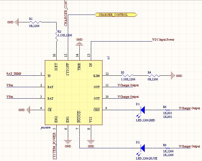
Other Parts Discussed in Thread: BQ24075

I wanna use TPS63002 to boost Li-ion battery voltage to fixed 5v, in order to power my Raspberry Pi3

I use WEBENCH tool to get the right values of Capacitors and Inductors, and the resulting circuit is attached here:

The resulting circuit could convert voltage and drive fixed 5v, but IC and the Inductor are overheating, and consuming 220mA!

Could you please tell me where is my mistake?

  • Can you replace the IC and test it again?
    Can you share the inductor datasheet?

    Could you share the layout?
  • Hi Sabrina and thanks for your suggestion
    I'll do that, but one thing that I just found today, is that the resistance between Pin number 2 (i.e. L2 pin), and GND is just 16 ohms, is it normal or not?
  • And the Inductor part number is AL0307-3R3K-LF
  • Looks like the low side mosfet of the output stage is damaged. There could be 2 reasons for L2 to break:
    either the layout is bad and the device is seeing lot of ringing for your operating conditions or this pin was overstressed (for example high voltage picks) during lab testing .

    What are the operating conditions? what is the end application?
    Could you share the layout?
  • Final Product will be a PDA based on Raspberry Pi 3

    I used a BQ24075 Charge Controller for Li Battery, and I wanna boost it's output via TPS63002

    Here is my circuit layout:

  • I saw that the board had some shortcut on it

    So, I modified that and replaced the chip with a new one

    Now, output voltage is 5v for currents lower than 100mA, but for larger currents, output voltage drops to 3v even if input voltage is 4.2v

    Do you know what is the main cause of this issue?

  • I would recommend to use an inductor with a saturation current of 1.5A enventhough the load is less.
    I would like to take a look at the PCB layout like the one shown on page 10 of the datasheet.

    Could you measure the input and the output voltage and share the measurement?
  • Yes, you're right, that was the PCB issue

    Now, with thickened and shortened tracks, and closer elements (Capacitors and Inductance), that issue is solved

    and we have stable 5v output, but until current is lower than 500mA

    For currents more than that, the output voltage goes up and down between 4.8v and 5v, and this causes problems for my USB Devices connected to Raspberry.

    Do you have any idea how to solve this issue too?

    The schematics is the same as before.

    Thanks

  • Could you repost you operating conditions :
    vin range?
    Vout = 5V?
    Load (min max)?

    I would need to see your PCB layout to help you further, you can send it to me by private message if you do not wish to share it on a public forum.
  • V_in: Lithium Battery Voltage (between 3.3 to 4.2)

    V_out: 5v

    Expected I_out: upto 0.9A

    Load: 0.1A upto 0.9A

    Schematics and PCB are:

  • Thanks for the layout

    I could not find output capacitor on the output of the device. This is most probably the reason the device is not behaving as expected. I would recommend to place an output capacitor close to the device in addition to the 49uF cap

    I would recommend to improve the layout, please follow the layout guidelines chapter 10 of the datasheet. It is critical to have a good layout to have a reliable design. Especially the input and output capacitors should be placed as close as possible to the device with a good ground connection

    Once modified I can help you review the layout before going to production.
  • Thanks, sure, I'll follow those instructions

    what capacity should be the that output capacitor?

    And, another question: what do you mean: "good ground connection" ? 

  • I would follow the datasheet recommendation and place a capacitance of 15uF (excluding the DC bias) at the output.

    good ground connection = shortest connection possible between the device PGND and capacitor gnd (as shown in the layout example), or place multiple vias at the capacitor ground in case the connection is not direct. This needs the capacitor to be placed as close as possible to the device