This thread has been locked.

If you have a related question, please click the "Ask a related question" button in the top right corner. The newly created question will be automatically linked to this question.

BQ76920: I2C Connection not establishing with AVR ATTiny24A

Part Number: BQ76920
Other Parts Discussed in Thread: ADC3424

I am using a Microchip Attiny24A controller as master and is establishing the communication with BQ76920 for protection of 3 series Cells.

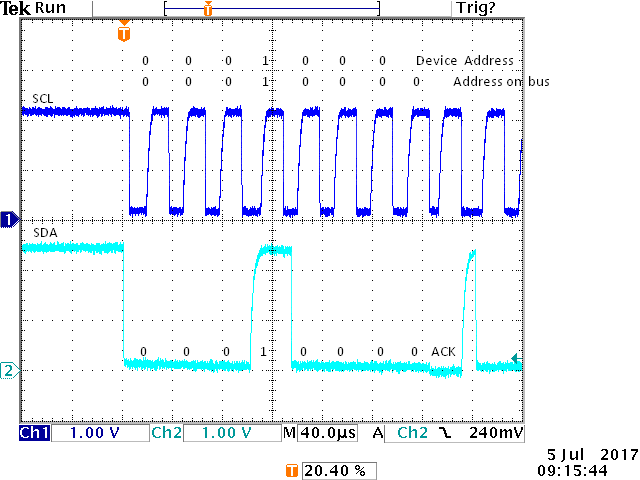
Trying to Communicate with it by sending the Device address as 0x08 as specified in the d/s for Part BQ7692000PWR.

Every time I receive a NACK after transmission of Device Address.  for rest of the data SDA and SCL are at HIGH state. couldn't understand the reason.

as for starting, I am resetting the SYS_STAT register to 0xFF, then setting CELLBAL1 to 0x13 (for 3s Configuration),  SYS_CTRL1 to 0x10 to enable ADC, in SYS_CTRL2 setting 0x13 to disable protection for the first time to Verify CHG and DSG  State working.

Can anyone suggest?

  • Hi,

    If the part has proper power it should ACK its address and communicate.  Remember that the address 08 is a 7 bit address, it looks like 10 on the bus as shown below.  Check that the tool for your MCU or peripheral are making the conversion properly. Also check that the levels and edges are ok.  Signaling from the MCU is likely to be much faster than that shown below.  If the MCU does not receive the ACK it likely stops thus leaving the bus signals high.

    For the registers, once you have communication established: 

    • Clearing the status register is a good idea
    • CELLBAL1 should not be set to 0x13 since this will attempt to balance all 3 cells simultaneously and could exceed abs max.  See the note in section 7.3.1.3.3 of the data sheet.  The register will default to 00 which is good for normal (non-balancing) operation, writing the register to 00 for initializaiton should be OK.
    • SYS_CTRL1 OK
    • SYS_CTRL2 bit 4 is reserved and should not be set. Protections can not be disabled (although voltage protections will not get a voltage update if the ADC is turned off).  A value of 0x03 will enable both DSG and CHG for testing if there are no faults.  Setting the DELAY_DIS bit for a value of 0x83 would allow faster response to faults for testing.

  • Bit 4 was confused in the reply above, it has been corrected.

  • Hi

    Thanks for the Reply,

    I am using 0x10 on the bus for the slave Address. Now, SDA is low and SCL is HIGH and is holding these states irrespective of Releasing of the Bus.

    the pulse HIGH Time and Low Time I am using is as follows, as specified in D/S
    #define I2C_TLOW 4.7
    #define I2C_THIGH 4.0


    unsigned char I2CAddress = 0x08; // device Address

    /**All the Declaration of functions here*/
    ----------------
    --------------
    ---------------

    char readRegister(unsigned char address)
    {
    unsigned char i2c_Add = (I2CAddress << 1) | 0x01; // appending read bit at the LSB shifting the I2C Address 1 bit left
    unsigned char readData;
    device(I2CAddress);
    I2c_write(address);
    device(I2CAddress);
    readData = I2C_read();
    I2C_stp();
    return readData;
    }

    void writeRegister(unsigned char address,unsigned char data)
    {
    unsigned char i2c_Add = I2CAddress << 1; // appending Write bit at the LSB shifting the I2C Address 1 bit left
    I2C_start();
    device(i2c_Add);
    I2c_write(address);
    I2c_write(data);
    I2C_stp();
    }


    char USI_I2C_Master_Transfer(char USISR_temp)
    {
    USISR = USISR_temp; //Set USISR as requested by calling function

    // Shift Data
    do
    {
    USI_I2C_WAIT_LOW();
    USI_CLOCK_STROBE(); //SCL Positive Edge
    while (!(PIN_USI&(1<<PIN_USI_SCL))); //Wait for SCL to go high
    USI_I2C_WAIT_HIGH();
    USI_CLOCK_STROBE(); //SCL Negative Edge
    } while (!(USISR&(1<<USIOIF))); //Do until transfer is complete

    USI_I2C_WAIT_LOW();

    return USIDR;
    }


    void I2C_start()
    {
    /////////////////////////////////////////////////////////////////
    // Generate Start Condition //
    /////////////////////////////////////////////////////////////////

    USI_SET_SCL_HIGH(); //Setting input makes line pull high

    while (!(PIN_USI & (1<<PIN_USI_SCL))); //Wait for SCL to go high

    #ifdef I2C_FAST_MODE
    USI_I2C_WAIT_HIGH();
    #else
    USI_I2C_WAIT_LOW();
    #endif
    USI_SET_SDA_OUTPUT();
    USI_SET_SCL_OUTPUT();
    USI_SET_SDA_LOW();
    USI_I2C_WAIT_HIGH();
    USI_SET_SCL_LOW();
    USI_I2C_WAIT_LOW();
    USI_SET_SDA_HIGH();

    /////////////////////////////////////////////////////////////////
    }

    char device(unsigned char msg)
    {
    USI_SET_SCL_LOW();
    USIDR = msg; //Load data

    USI_I2C_Master_Transfer(USISR_TRANSFER_8_BIT);
    USI_SET_SDA_INPUT();
    if(USI_I2C_Master_Transfer(USISR_TRANSFER_1_BIT) & 0x01)
    {
    USI_SET_SCL_HIGH();
    USI_SET_SDA_HIGH();
    return 0;
    }

    USI_SET_SDA_OUTPUT();

    }

    char I2c_write(unsigned char *msg)
    {
    USI_SET_SCL_LOW();

    USIDR = *msg; //Load data

    USI_I2C_Master_Transfer(USISR_TRANSFER_8_BIT);

    USI_SET_SDA_INPUT();

    if(USI_I2C_Master_Transfer(USISR_TRANSFER_1_BIT) & 0x01) // NACK BIT
    {
    I2C_stp();
    return 0;
    }

    USI_SET_SDA_OUTPUT();
    return *msg;
    }

    char I2C_read()
    {
    unsigned char *msg;
    USI_SET_SDA_INPUT();
    *(msg)= USI_I2C_Master_Transfer(USISR_TRANSFER_8_BIT);
    USI_SET_SDA_OUTPUT();

    //if(msg_size == 1)
    {
    USIDR = 0xFF; //Load NACK to end transmission
    }
    //else
    {
    USIDR = 0x00; //Load ACK
    }

    USI_I2C_Master_Transfer(USISR_TRANSFER_1_BIT);

    return *msg;
    }

    void I2C_stp()
    {
    /////////////////////////////////////////////////////////////////
    // Send Stop Condition //
    /////////////////////////////////////////////////////////////////

    USI_SET_SDA_LOW(); // Pull SDA low.
    USI_I2C_WAIT_HIGH();
    USI_SET_SCL_HIGH();
    while( !(PIN_USI & (1<<PIN_USI_SCL)) ); // Wait for SCL to go high.
    USI_I2C_WAIT_HIGH();
    USI_SET_SDA_HIGH(); // Release SDA.

    while( !(PIN_USI & (1<<PIN_USI_SDA)) ); // Wait for SDA to go high.
    USI_I2C_WAIT_LOW();

    }

    int main(void)
    {

    //master initialize
    DDR_USI |= (1 << PORT_USI_SDA) | (1 << PORT_USI_SCL); // set PA4 (SCL) & PA6(SDA) as o/p pins
    PORT_USI |= (1 << PORT_USI_SCL); // release SCL & SDA
    PORT_USI |= (1 << PORT_USI_SDA);
    USIDR = 0xFF;
    USICR = (0 << USISIE) | (0 << USIOIE) | (1 << USIWM1) | (0 << USIWM0) | (1 << USICS1) | (0 << USICS0) | (1 << USICLK) | (0 << USITC);
    USISR = (1 << USISIF) | (1 << USIOIF) | (1 << USIPF) | (1 << USIDC) | (0x00 << USICNT0); // Initializing I2C at Attiny

    while (1)
    {
    writeRegister(0x00, 0xFF); // clearing SYS_STAT /// HERE I AM STUCK. SDA is LOW and SCL is Constant HIGH when at BUS I send 0x10. in case of 0x08 I get NACK.
    /// rest of the code
    }
    }


    Any suggestion ? what I am doing wrong ?
  • In Addition to above . I have verified the I2C Communication of Attiny24A with ADC3424. and verified the working of BQ76920 with Arduino Mega 2560. both are working individually. but there is a communication problem in between ATTiny24A and BQ76920.

    Any thing which I have missed ??
  • Hi Bilal,
    Unfortunately I'm not able to provide coding support. The AVR community may have good advice on setting up the peripherals, coding characteristics for the processor, or specific recommendations on I2C debug with that processor.
    In general you may need to look at the bus to see who is driving it. If the bq76920 is holding the bus low it may have set the ACK and be holding it waiting for a clock, or may have started outputting data from a read. The standard bus-release mechanism in I2C is to send (up to 9?) clocks until the slave releases the bus. If the host is holding the SDA line it may be a peripheral setup issue.
  • Hi
    I did make a check on the Connections, it was found that I was not Rebooting the Device to NORMAL Mode, also for Communication to Attiny, instead of sending the Data to the Line directly. I made use of a Buffer variable to send the data linearly and properly. it is now able to communicate with BQ76920

    For Code Help I referred to the Arduino Library Functions. 

  • Another suggestion here use ATTINY 84A instead of 24A there is a memory issue. One has to compromise some of the protection using 24A.