This thread has been locked.

If you have a related question, please click the "Ask a related question" button in the top right corner. The newly created question will be automatically linked to this question.

WEBENCH® Tools/UCC28630: difference between dot directions in transformer report and schematic

Part Number: UCC28630

Tool/software: WEBENCH® Design Tools

Hi, All.

I'm trying to design SMPS with UCC28630 using the WEBBENCH design tool and have a question about dot directions of transformer.

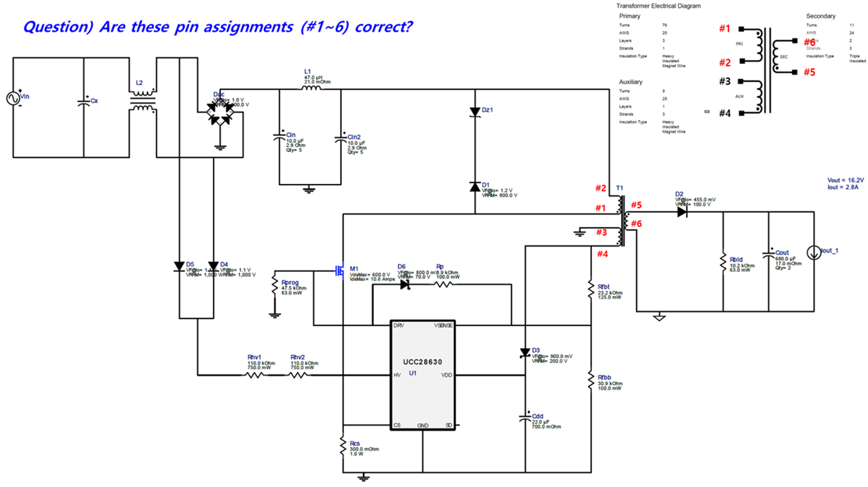
Using WEBBENCH, we can get a schematic and a transformer report both for a given design, however, as I was using UCC28630, dot directions in the schematic and the transformer report are different as shown in diagrams attached below.

I'm not sure if the dot directions in the transformer report are correct and it is just used in the schematic by changing pin arrangements. Could you let me know where this difference comes and how I have to use it correctly?

  • Kyuate, the dot notations are the same in both of these diagrams. You can see that the dots are opposite the same pin numbers in each case. The pins are just rearranged graphically in the schematic. 

    As shown, pins 1, 4 and 5 should be wound in phase with each other. 

    Thanks

    Billy

  • Hi Billy. Thank you for the comment. Just for a re-check, how about the case in which the pin numbers were not shown in the diagrams? Are those two transformer diagrams still same? The reason why I'm asking same question is that the pin numbers in the attached diagrams were assigned by myself to explain my understanding on the difference between two diagrams. Thanks!
  • Kyuate, the dot notations are the same in both of these diagrams. You can see that the dots are opposite the same pin numbers in each case. The pins are just rearranged graphically in the schematic. 

    As shown, pins 1, 4 and 5 should be wound in phase with each other. 

    Thanks

    Billy

  • Hi Hyutae,

    Thanks for reaching us on E2E, and yes your understanding and labelling was correct. The transformer report downloaded from Webench does not have any pin assignment, it only offers the key transformer parameter for transformer design and manufacturing.  This allows user and transformer manufacturer to have the freedom to select their pin assignment for the transformer, the dots are only indicating which ends would be in phase. 

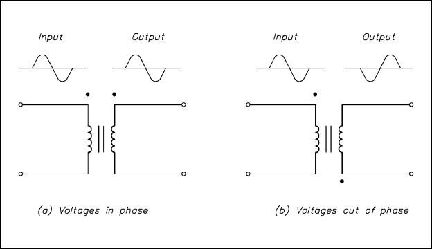
    The dot notation of the transformer is an indication of which ends of the transformer would have the same polarity i.e. in phase. The picture illustrated below gives a clear indication of the dot notation when a sinusoidal signal is applied:

    I hope this would help to clarify your questions.

    Best Regards,

    Wei-Hao Chen

  • Hello All.

    I have big problems with this design I posted about UCC28630. Could you please check my questions below about the problems I've faced, and let me know if you have any good idea to solve these problems?

    problem #1. As 220VAC is applied, 300VDC is appeared at pin #2 of primary side of the transformer, but no voltage appears at pin #5 of secondary side of the transformer.

    problem #2. After then, as AC plug is removed, substantial charges still remains in the circuit, and it is discharged with considerable shock as we touch some components such as a heatsink of M1 or some solderings / pins in the primary side of the transformer. As you might imagine, it's very dangerous for us to debug.

    For your reference, I have made the PCB board with exactly same circuit design of UCC28630, I'd posted.

  • Hi Billy.

    I have big problems with this design I posted about UCC28630. Could you please check my questions below about the problems I've faced, and let me know if you have any good idea to solve these problems?


    problem #1. As 220VAC is applied, 300VDC is appeared at pin #2 of primary side of the transformer, but no voltage appears at pin #5 of secondary side of the transformer.

    problem #2. After then, as AC plug is removed, substantial charges still remains in the circuit, and it is discharged with considerable shock as we touch some components such as a heatsink of M1 or some solderings / pins in primary side of the transformer. As you might imagine, it's very dangerous for us to debug, so we need more good approach to solve the problem.


    For your reference, I have made the same PCB board with this circuit design of UCC28630 I attached at my first posting.
  • Hi Kyutae,

    Thanks for reaching back to us again. Please see below for some comments regarding the problem you have faced.

    Problem 1: Could you please check the Vds of the primary side FET to see if the FET is switching?  

    Problem 2: This is because when the plug is removed, there are still some remaining charges restored in the bulk capacitors on the primary side. It would take some time for it to be completely discharged, or you may manually build a little discharge circuit to discharge the bulk cap before debugging. Please refer to the useful link below: https://www.ifixit.com/Guide/Constructing+a+Capacitor+Discharge+Tool/2177

    Thanks!

    Bes Regards,

    Wei-Hao Chen

  • Hi Wei-Hao.

    Thanks for your kind help.

    For the problem 1, I've posted in another posting with more updated information as linked below. It would be very appreciated if you could also give me a kind help for the questions in the link!
    e2e.ti.com/.../612639

    For the problem 2, I will make it! Thanks!
  • Hi, Wei-Hao.
    The information you told me about the discharge tool was very helpful for me proceeding circuit debug. I really appreciate to your kind help!!
  • Hi Kyutae,

    You are most welcome, I am glad I could be of help.

    Best Regards,
    Wei-Hao