This thread has been locked.

If you have a related question, please click the "Ask a related question" button in the top right corner. The newly created question will be automatically linked to this question.

UCC2800: Max VCC

Part Number: UCC2800

The extended range datasheet has note: "In normal operation, VCC is powered through a current limiting resistor. Absolute maximum of 12 V applies when VCC is driven from a low impedance source such that ICC does not exceed 30 mA (which includes gate drive current requirement)."

Is the intent of the note to limit power dissipated in the chip? If so, is there any further information? If not, what is the intent of the note?

Thank you!

  • Hi Clare,

    Thank you for interested in TI and reaching us on E2E.  

    The statement written in the datasheet was intended to ensure the power dissipation across the internal resistor does not exceed its thermal limit and prevent further damage on the IC.

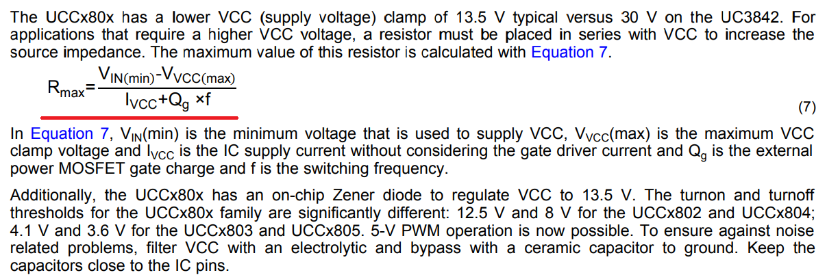
    Further information regarding the VCC supply can be found in Section 9.3.1.7 VCC on the bottom of page 13 of the UCC2800 datasheet. An external resistor must be placed in series with the VCC pin to reduce the power dissipation on the internal resistor if a low impedance voltage source is applied, the external resistor value can be calculated using Equation 7:

    I hope this would help to clarify your question. Please do not hesitate to let us know if there is anything else you are interested.

    Thanks a lot.

    Best Regards,

    Wei-Hao Chen

  • Thank you for the response.

    As a followup question, section 9.3.1.7 discusses the max resistor that can be used, but does not specify the minimum. If the resistor internal to the IC on VCC must be protected, how much power can it dissipate? Does the resistor limit the current through the zener?

    Thank you.
  • Hi Clare,

    I have just confirmed this with the designer of UCC2800 regarding the VCC current limiting resistor, and I am sorry I have misinterpreted the statement.

    There is NO internal current limiting resistor. The external resistor is required to limit the VCC current through the device to reduce the stress and power dissipation on the internal Zener diode if the VCC supply voltage is greater than Zener clamp voltage i.e. 13.5V

    The minimum external resistance required can be calculated using: 

    On the other hand, Equation 7 calculates the maximum resistance allowed to provide the sufficient supply current for the gate drive and bias current of the device.

    The maximum power dissipation rating of the device is 405mW (13.5V x 30mA).

    I hope this would help to answer your question and I apologise for the confusion in the first place.

    Thank you.

    Bes Regards,

    Wei-Hao Chen