Because of the holidays, TI E2E™ design support forum responses will be delayed from Dec. 25 through Jan. 2. Thank you for your patience.

This thread has been locked.

If you have a related question, please click the "Ask a related question" button in the top right corner. The newly created question will be automatically linked to this question.

BQ25120: Fanout without using via

Part Number: BQ25120
Other Parts Discussed in Thread: BQ24230, BQ25121,

Hi

In another topic this IC was recommended to me:


It comes only in 0.4 pin pitch BGA packaging.
I'm using a PCB with 8D class which does not handle such tiny via.
But then I noticed that the pads were arranged in a interesting way, so I wanted to see if it can actually be done without using any via at all.
Here is an image of what I came up with:
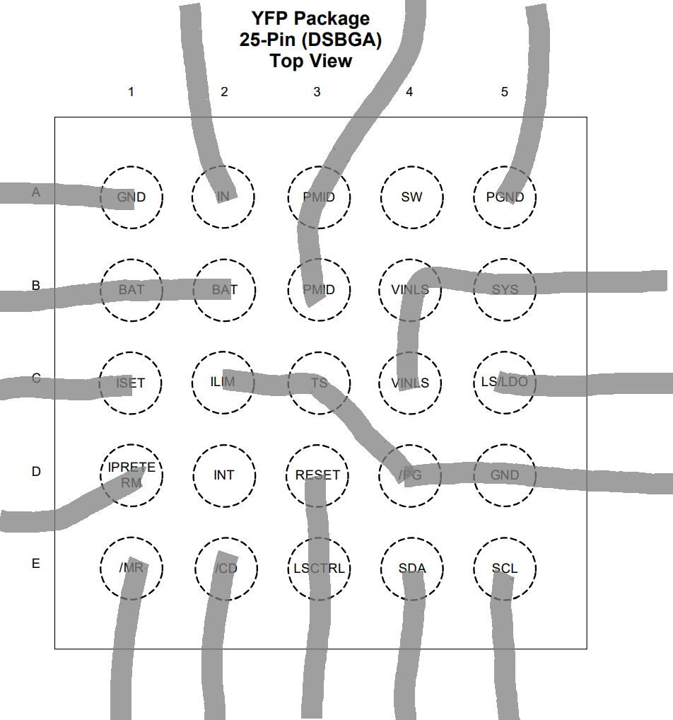

Its just a paint sketch, but it illustrates what I had in mind.
It sacrifices some features, like TS, but I did not plan to use it anyway, since I already have a dedicated temperature sensor for other reasons.
The question now is can this work, or does it introduce problems with the basic functionality. The buck switching is also unused.

Also, I find it a bit unclear, what is the output voltage of the LDO when the IC has not been initialized and tied with reset like shown above?

  • Hello,
    Regarding basic functionality, you have to connect an inductor and capacitor to the output of SW or the device wouldn't work. Also since VSYS is set to 1.8V by default, the voltage at the LS/LDO pin will be 1.8V. To achieve a higher voltage through I2C, you should connect VINLS to PMID which follows the higher of VBAT or VIN. Having TS grounded will result in a TS fault. This will have to be disabled through I2C if you don't intend to use it. The default voltage of the LDO will be 1.8V.
    -Raheem
  • Hi!

    Thanks for the reply!
    What exactly prevents the IC from working without the coil? I've been looking into the datasheet and I can'f find why is that.
    Can it be hacked so I don't have to include it in the BOM as I don't need that feature?
  • Hello,
    The internal buffers inside the IC are connected to SYS. If you look at the schematic, SYS is connected to the output of the Buck. Unfortunately, you have to include the inductor and the capacitor. If you don't have to use the LDO, you can check out the BQ24230 if this doesn't work.
    -Raheem
  • Ok, so this is what I came up with for now:


    It is like you said it should be.
    The values of components have not been adjusted yet.
    Is the schematic above acceptable?

  • Hello,
    The only problem I see is that the R18 resistor should be removed. PMID is unregulated and SYS is so you don't want to short them together. Also if you want to charge the batteries in parallel, ensure that they have similar ratings and manufacturers.
  • Yes, R18 is a bit odd, I left it as a jumper just in case. I put it there because the post above said " you should connect VINLS to PMID which follows the higher of VBAT or VIN". Otherwise I do have a 3.7 to 3.3V regulator, and I will try to see if I can get without it starting up from the LDO default voltage.
    The batteries will be identical models, installed simultaneously and non removable, so I think they should work fine. The structure of the device does not allow for other battery configurations.

  • Dajgoro,

    Yes that is correct. VINLS should be connected to PMID. I would suggest you connect VINLS to PMID and disconnect the connection between SYS and VINLS. Place C41 at SYS.

    -Raheem

  • Dajgoro,

    Another thing is that your CD pin should be connected to your MCU. Are you using the BQ25120 or the BQ25121?

  • I find the description of the CD pin extremely confusing, in that text it sounds like CD should be kept high, on the CD pin description it sounds as the CD pin should be kept low. I'm using the BQ25121. I don't want to disable the chip at any point, except for when entering in ship mode. I don't want to be able to disable charging here, because I'm already using a wireless power receiver (BQ51013BRHL) and I disable it rather there than on the BQ25121 so that it can stop the wireless power transfer.
    From the description on page 26 "9.3.20 Chip Disable (CD)" I figured I can just leave the pin not connected since it is pulled down to ground leaving the charging enabled. I also looked in the manual of the eval board, and it showed the CD jumper should be left unconnected for enabling charging.

    Also, if I connect the CD to the mcu, and disable the chip, thus cutting power, how do I ever re-enable it again?
  • Dajgoro,

    CD is internally pulled low so if you don't control CD, the part will go into HI-Z mode whenever you remove VIN. You need the MCU to control this so that you can drive CD = HI when charging is done this way, when VIN is removed, you go into active BAT mode. If CD is always kept high, you'll never charge the battery. Regarding not being able to re-enable power to the chip, that's exactly why you need MCU control. You use the MCU control to ensure you're never in this state like I've stated. Also, is there any reason why you picked the BQ25121 over the BQ25120?

    -Raheem

  • Oh, ok. I'll connect CD to the MCU then, thanks.
    The  BQ25121 has 2.5V as DEFAULT SYS OUTPUT which is suits me better, even tho I can adjust it via sw once the MCU has initialized.

  • I got the pcb-s and it seems to work, except one small problem.
    I can't get the reset output from the PMIC to work.
    The mcu gets bit buggy as it seems if reset is not asserted properly.
    I tried all sort of register configurations, but I can't get it to forward the reset signal from the MC input.
    I have the same issue on multiple boards.
    The reset output is not stuck to vcc or something like that, it only goes to the LDO enable input, but that should not affect it in any way.
    The button works, because when its set into ship mode, and the button is pressed, power is resumed.


    The issue has been resolved now, did a bunch of changes, not sure which one fixed it.

  • Dajgoro,
    Great. Glad it works.
    -Raheem