Other Parts Discussed in Thread: PMP6712, PMP8606
Hello
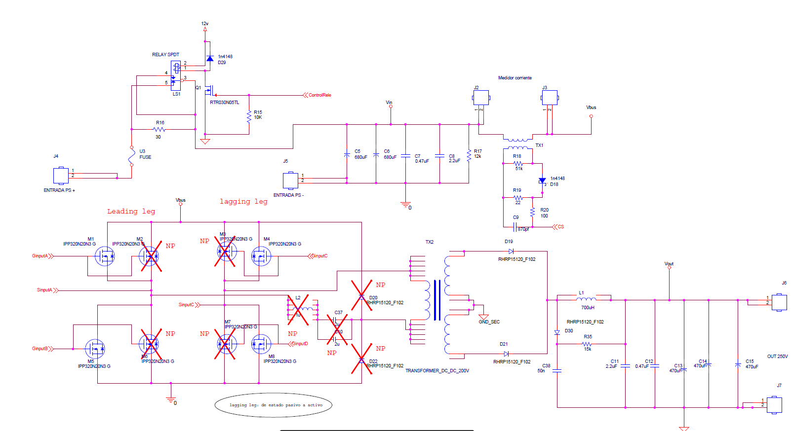
I am designing a DC / DC 150V input source and a 250V output, at a power of 1200W. At the moment I do not have a 150v DC source, therefore using the same hardware calculated for a 150V input and a 250V output, I am using a 30Vdc input source and a 65V output, obviously limiting the power to 150W. All this I do to test the operation of the UCC28950 controller.
To sense the current, I am developing a current sensor with ferrite toroids that I find in the local market. The toroids used are of T38 material of epcos and the other has no specifications. I give 100 turns to both and I get approximately Lm = 30mH, in both cases.
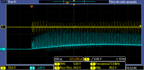
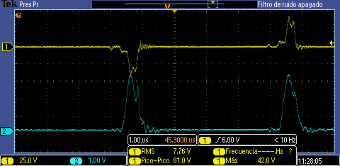
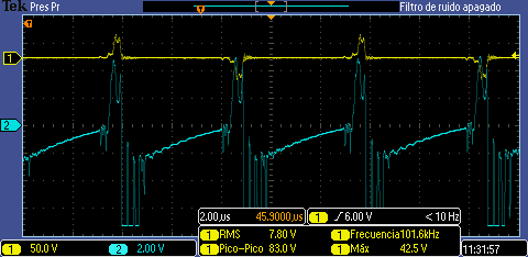
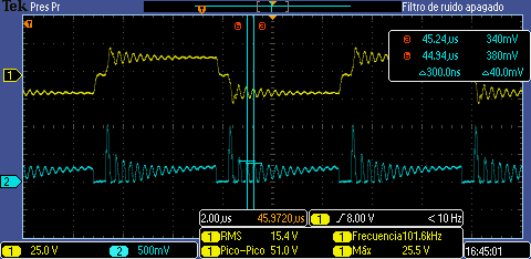
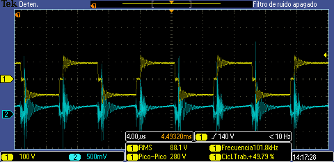
The problem is the same in both transformers, because a DC level appears in the output signal (see image). This DC level prevents me from controlling the circuit, because the more the load increases, the DC level increases, reaching the 2V level of the pin cs too fast.
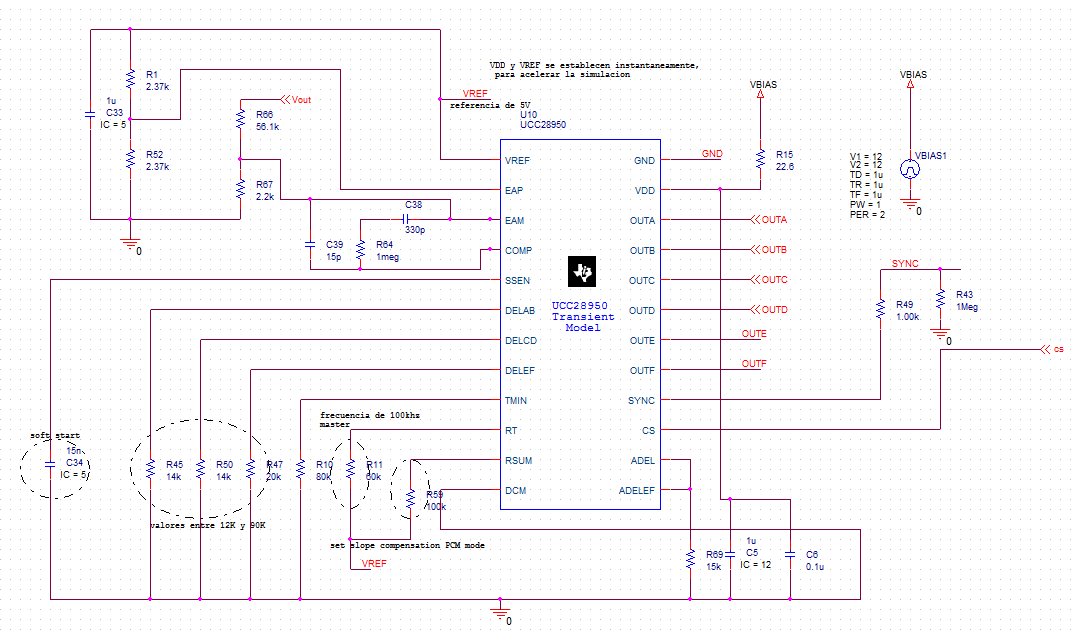
I'm implementing the circuit found in the UCC28950 data sheet, and the circuit on the PMP6712 board is also implemented, but the result is the same in both cases. I suspect that the transformer can not be reset.
What should be the selection criterion for the core? Or is there a problem with the circuit that I have implemented (see image)?
Thanks.
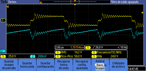
(Cs waveform)

(Cs circuit)