This thread has been locked.

If you have a related question, please click the "Ask a related question" button in the top right corner. The newly created question will be automatically linked to this question.

LM5088: Request for Schematics verification - LM5088-2 device

Part Number: LM5088

Dear All,

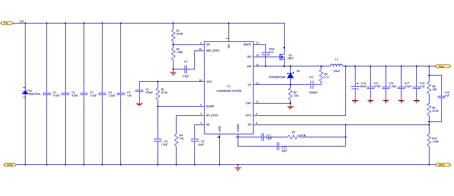
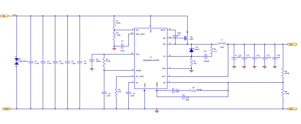
one of my customer working on LM5088-2 device for DC -DC Converter for below specs - they done schematics and request you to review and advise your valuable feedback.

Input voltage: 40V-70V

Output voltage: 19.5V, 5A

Rgds,

Aravind. 

  • I don't see any schematic errors. I do recommend retaining the 10 ohm injection resistor (R7 in data sheet figure 27) above the upper feedback divider resistor. The injection resistor allows you to validate the loop response of the design. If room allows, I would also include pads for a capacitor across the upper feedback divider resistor, as a just-in-case no cost addition. Make sure there is plenty of heat sink area for the diode and the MOSFET. They might consider a dual diode package to help spread the heat out. It would make more sense for the input Transzorb to be unipolar.
  • Dear Alan,
    Thanks for your valuable feedback - I would like to interact with you personally over email for layout verification - please do needful.
    Also customer configured LM5088MH-2EVAL/NOPB for 19.5V/6A as per webench design values - bu converter seems to restart repeatedly.
    below are component values customer changed for 19.5V - please advise your valuable feedback

    19V
    Part Part Number Quantity Attribute 1 Value Footprint
    C12 GRM1885C1H182JA01J 1 1.8nF, 50V 0603
    R4 CRCW060364K9FKEA 1 64.9kOhm 0603
    R9 ERJ-3EKF1651V 1 1.65kOhm 0603
    R8 ERJ-3EKF2492V 1 24.9kOhm 0603
    R10 RC0603FR-0795K3L 1 95.3kOhm 0603


    Rgds,
    Aravind.
  • Dear Alan,

    Look forward for your feedback on above post - customer made changes in schematics as per suggestion given by you - please find attached same - help to review and advise.

    Aravind.

  • Hi Aravind,

    I haveforwarded your request to the responsible team . They will get back to you in a day or two .

    ---Ambreesh
  • Hello,

    Here are the values I recommend for modifying the EVM.

    1. Rcomp = 20k

    2. Ccomp = 4.7nF

    3. Rramp = 86k

    4. Cramp = 560pF

    Things to watch out for when modifying the EVM.

    Make sire that the ISat capability of the inductor can handle the peak currents at max Iout.

    In your case will be 10A++

    Make sure that the Cout voltage rating is 25V.

    Hope this helps?

  • Dear Sir,

    Thanks. I also need help to share layout/gerber files for EVM# LM5088MH-2EVAL/NOPB - please do needful.

    I need help on attached schematics to be reviewed - which customer modified based on suggestions from Mr.Alan.

    Rgds,

    Aravind.

  • Please can you email me for the layout files for EVM.

    David.Baba@ti.com

    Thanks.