This thread has been locked.

If you have a related question, please click the "Ask a related question" button in the top right corner. The newly created question will be automatically linked to this question.

TPS23861: POE Classification Issue

Part Number: TPS23861
Other Parts Discussed in Thread: TPS23756EVM, TIDA-00465, TPS23756

Hi Everyone!

I've used only the single port of "TPS23861" in Auto mode configured with iMX6 as host processor. I used "TPS23756EVM" as PD to test the functionality of our design. I am facing issue that whatever is the classification resistor i'm using at "R9" in TPS23756EVM, it's always showing the class 0 at CLI and there is always one event classification happening irrespective of the CLS resistor value i used at "R9" on PD. If i'm not wrong there should be 2-event classification when the PD used is class 4 (802.3at compliant).

If i connect a load more than 15W the PSE limits the port current to ILIM current limit which is changing from class 0 to class 3 with the corresponding R9 value at PD. But, It's not sourcing the 802.3at mode current to a valid class 4 PD. I want to use our PSE controller in auto mode as the PD could either be 802.3af or 802.3at compliant.

Please tell me why it's not detecting a class 4 PD accurately. Please let me know if there is anything i'm missing in hardware or software configuration.

  • Hi Sanjeet,

    Yes. Your understanding is correct. If the TPS23861 finds class result is class 4, it will automatically send 2 event classification and set the right current limit threshold. I think your problem here is why the PSE always gets class 0. Can you confirm 63.4ohm is used for R9? Did you use TPS23861EVM? If not, can you send me your schematic? Thanks.

    Best regards,

    Penny

  • Hello Sanjeet,

    I have notified our expert and we will have a response for you, shortly.

    Thanks,
    Thomas Amlee
  • Dear Penny Xu,

    First of all thanks for giving your time to my query. I'm glad to get quick response from you.

    I used actually mounted resistor on the TI's "TPS23756EVM". Which is designed as a 802.3at compliant PD. I also manually checked the resistor value to be double sure. As of i now i don't have "TPS23861EVM".  Please find my schematic attached here.PSE_CONTROLLER_SCHEMATIC.pdf

  • Hi Sanjeet,

    I have a couple comments on the schematic:

    1. Please change sense resistor R927 to 255mohm. It impacts the current measurement accuracy.
    2. Please remove R954 and C411 since they are not needed.
    3. Please make sure you set the UVLO of TPS7A4001DGN to >18.5V. TPS23861 requires power on sequence(www.ti.com/.../slva723.pdf).

    We have single port reference design on ti.com. Please search TIDA00465.

    Please let me know if you still have problems after making the changes above. Thanks.

    Best regards,
    Penny
  • Hi Penny,

    A debt of gratitude is in order for your review comments. Please find the inline response for those:

    1. Please change sense resistor R927 to 255mohm. It impacts the current measurement accuracy.
    :- I replaced sense resistor R927 by two parallel 500mohm, 1W, 1% resistors to make an equivalent of 250mE due unavailability of single 255mohm resistor. In "TIDA-00465" also they are using 2 parallel resistors of 510mohm in parallel.

    2. Please remove R954 and C411 since they are not needed.
    :- I removed the above components & directly connected the Gate1 pin of TPS23861 to MOSFET's gate.

    3. Please make sure you set the UVLO of TPS7A4001DGN to >18.5V. TPS23861 requires power on sequence(www.ti.com/.../slva723.pdf).
    :- I missed this in schematics but, it has been taken care by externally mounting a 2.2uF capacitor across RESET# pin of TPS23861 to delay the reset release time. I've checked the POR after rework & it's appropriate now.

    I've compared my design with TIDA-00465, it's similar to that.

    After all above reworks i again checked the functionality. But, i didn't get any improvement & the board is still operating in 802.3af only irrespective of the classification resistor value (63.4 ohm) mounted on PD.

    I request you please look further in to this matter to help me know about the cause of the issue & resolve it.
  • Hi Sanjeet,

    I need more information to find the root cause.
    I think our local support team is going to order one TPS23861EVM for you to help debug. If not, please ask them to do so.

    Can you show me where "POE_RTRN 7" is connected to? In your schematic I only see "POE_RTRN_1" and "POE_RTRN_2" are connected to the data transformer.

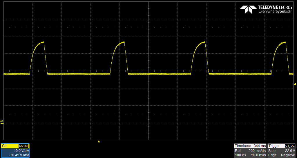
    Can you capture some waveforms of port voltage(Vdrain-Vpwr) under both conditions: when nothing connected to the port and TPS23756EVM connected to the port?

    I see you are also using host control. Can you dump all the register status of TPS23861 after you connect TPS23756EVM and send to me? Thanks.


    Best regards,
    Penny
  • Hi  Penny,

    Thanks to you & TI support team as they ordered an TPS23861EVM today. I hope the same will reach us within a day or two.

    Can you show me where "POE_RTRN 7" is connected to? In your schematic I only see "POE_RTRN_1" and "POE_RTRN_2" are connected to the data transformer.

    I sent you only 2 pages from my schematic which are related to PSE controller to avoid unnecessary information for ease of understanding. In actual it's a 22 page schematic. So, the digit 7 in "POE_RTRN 7" represents only the page number on which the same signal is travelling just like you can see the digits "13,15,17" for the signal "13,15,17 I2C2_SCL" as this I2C clock is travelling to these pages connecting to different ICs & host processor. So please don't think about the letters which are written after space/gap in signal names. I hope this will mitigate the confusion. If required i can send you the complete or updated schematic for PSE section.

    Can you capture some waveforms of port voltage(Vdrain-Vpwr) under both conditions: when nothing connected to the port and TPS23756EVM connected to the port?

    I'll send this to you by tomorrow.

    I see you are also using host control. Can you dump all the register status of TPS23861 after you connect TPS23756EVM and send to me?

    I'll send this to you by tomorrow.

  • Hi Penny,

    I've captured the waveforms of port voltage(Vdrain-Vpwr) under both conditions: when nothing connected to the port and TPS23756EVM connected to the port. With these I've attached the waveform captured for detection & classification event at the time of connecting TPS23756 PD to the Ethernet port. The classification resistor value at PD is 63.4ohm. Please check these & guide me to know about the root cause of the issue i'm facing. Let me know for any other information/waveforms required for better understanding.

    Thanks!

    PFA for the same.TPS23861_VDRAIN_VPWR_WAVEFORMS.zip

  • Hi Sanjeet,

    The drain voltage doesn't look good to me.   Where did you probe when measuring the drain voltage(can you point out on the schematic)? I am wondering why you have both positive and negative voltage on your drain voltage waveform.   The drain voltage should look like Figure 24 in datasheet when connecting a PD.  When open circuit, the port detection voltage(Vpwr - Vdrain) should be ~19V, so the drain voltage should look like this.

    Best rgeards,

    Penny

  • Hi Penny Xu,

    Please find the Vpwr-Vdrain & Vgate waveforms for both the cases when there is no PD connected & when we connect a PD. The Drain voltage is probed at :R155" & gate is captured directly across the gate of the MOSFET "Q3". When open circuit, the port detection voltage(Vpwr - Vdrain) is almost ~19V. But, the issue is that now we are getting multiple no of classification events before the controller delivers power to the PD.

    In EVM we observed very good rectangular waveforms for 1 or 2 event classification. I have compared the schematic of both & made the small suggested changes (NM "R954", "c411" & changed "R927" to 2 parallel resistors of value 500mohm) in our design. Still the behaviour is entirely different. Please have a look in to the attached waveforms & suggest what is causing this improper behavior in our design.  PSE Controller Waveforms.zip

  • Hi Sanjeet,

    Sorry for the late reply. Is this problem resolved? I saw there's I2C bus hooked up. Could you please read register 0x0C and check classification status?

    Best regards,
    Penny
  • Hi Penny,

    An obligation of appreciation for your incessant help. The issue has been resolved because of your superb guidance. I'm sorry for not updating you about this.

    Thanks!

  • Hi Sanjeet,

    Thanks for the updates! Great to hear it was resolved. Have a nice day.

    Best regards,
    Penny
  • Hi Penny,

    Could you please explain the difference between ICUT & ILIM interrupts. How can i test & verify both on my board? Please explain.

  • Hi Sanjeet,

    Following the end of the tSTART period a two-tiered current-limit protection scheme is applied to the ports. The first level (i.e., lower current) is the ICUT current limit. The ICUT current-limit threshold is set using the ICUTnm CONFIG registers and includes a timeout, tOVLD, set using TICUT field in the TIMING CONFIGURATION register. When the TICUT timer times out because the ICUT current threshold is exceeded, the port is powered off, and the ICUTn bit in the FAULT EVENT register is set with the option of asserting an interrupt. This delay in powering down the port provides protection against spurious power downs during moderate load transients.

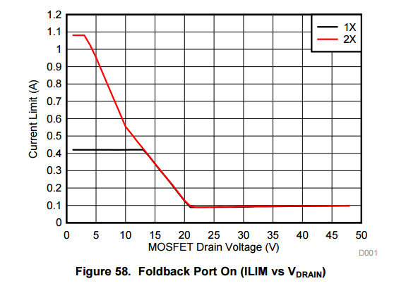
    The second level of powered-on current-limiting protection is the ILIM current limit. The ILIM current limit is a hard limit. That is, hardware protection including voltage foldback is imposed when the ILIM current threshold is reached. This second level of protection is invoked in the event of extreme overload or short circuit. The ILIM current-limit value is set using the POEPn bits in the PoE Plus register. Also, when the ILIM value is reached, the ILIM timer is started. When the ILIM timer times out, the port is powered off and the ILIMn bit in the Start/ILIM Event Register is set with the option of asserting an interrupt.

    PoEPn bit should be set according to ICUT value for host to ensure the ICUT and ILIM relationship (Check Table 15 in datasheet). Additionally, If ILIM and ICUT are set to same value, it is a race condition between ILIM and ICUT in TPS23861 and it depends on the firmware as to the winner.

    We have an FAQ page for TPS23861 if you want to know more about TPS23861 . e2e.ti.com/.../3489.tps23861-faqs. Thanks.

    Best regards,

    Penny