This thread has been locked.

If you have a related question, please click the "Ask a related question" button in the top right corner. The newly created question will be automatically linked to this question.

TPS53515: About function of mode pin

Part Number: TPS53515

Hi,

Let me talk about mode pin.
Is this pin involved in phase compensation?
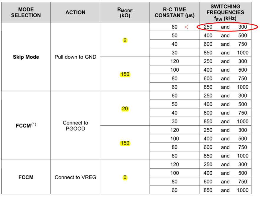
The R-C time is different for each Rmode value.
The function of the MODE pin is not only the switching function between PWM and PFM.
Is this correct?
Could you give me your advice?


Best Regards,
Yusuke/Japan Disty

  • As I know, the DCAP don't need the compensation in MODE pin. the MODE pin is just for the switching function choosing(FCCM or Skip-Mode).
    Select a MODE pin configuration to use single R-C time constant option for the normal (or smaller) output capacitance design and application.
    The Table about the MODE pin configuration give the suggestion for the maximum output capacitance design and application.
  • Yes it also selects the RAMP coefficient for DCAP3 as well as the frequency and FCCM or skip mode.
  • John-san,Mao-san,

    Thank you for your support.
    I am confused by your explanation.

    Does the resistor value of the mode pin have function of adjusting the ramp speed?
    If so, I think it involves phase compensation.

    I thought the lamp depended on the operating frequency.
    Could you give me you advice?


    Best Regards,
    Yusuke/Japan Disty

  • The Rrf_h and Rrf_l resistor divider from VREG to GND connected to pin 1 RF sets the switching frequency according to Table 1. The MODE pin has three main set options; Skip mode, FCCM after PWRGD goes high and FCCM all the time. Additionally there are two sub options for each, normal RC time constant and double RC time constant. The double RC time constant is used for larger output capacitance. The time constants are different for each of the four frequency ranges to ceep teh ramp amplitude approximately constant.